Club Meeting: 7 Aug 2024
Report by: Ian Connelly
Glenn started by saying the inspiration for this was a youtube by Ronald Kanne.
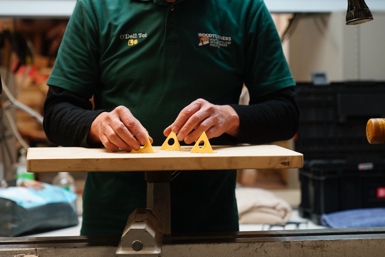
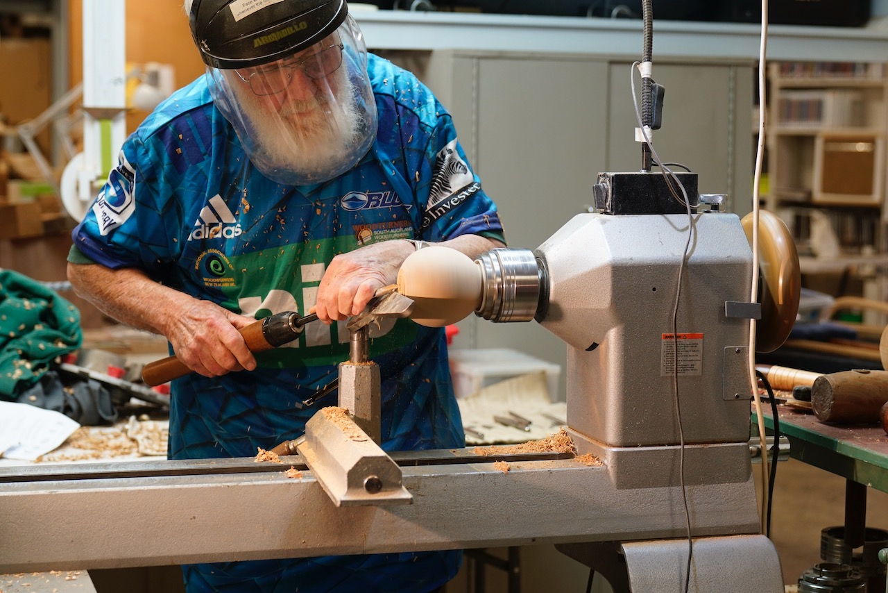
He started by mounting the blank on a worm screw, rounded the timber and marked the centre, as well as 30mm either side of centre. Another mark was put 20mm down the side of the blank on either side. These marks were used to take the corners off the blank
The design involves turning out the centre then putting an insert in each side of the flask. This insert area was marked at 105mm.
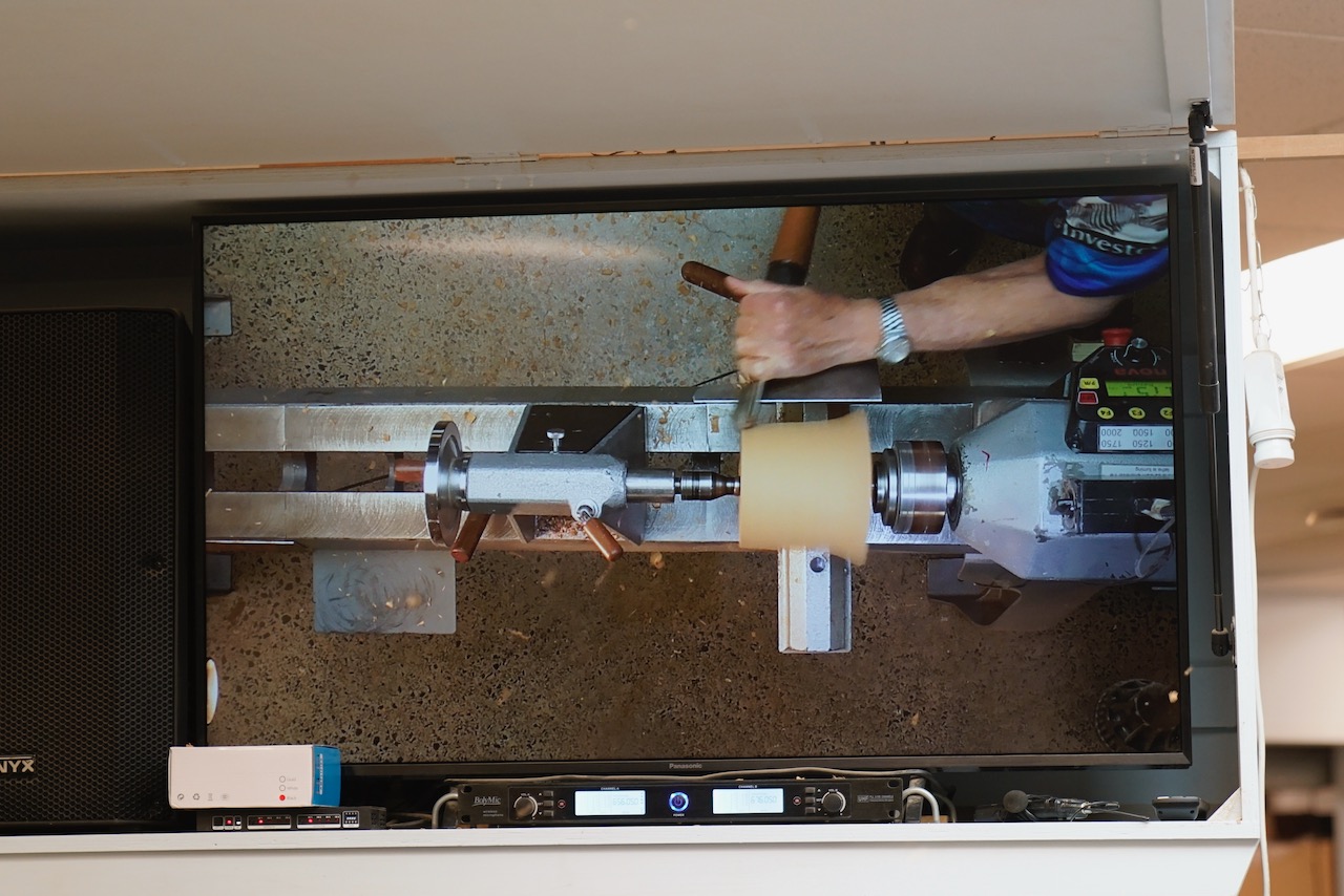
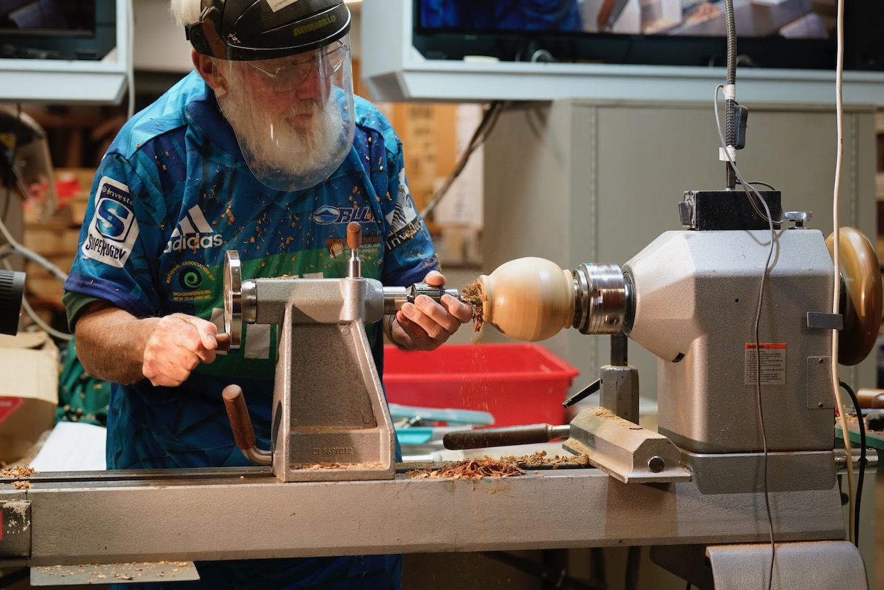
Glenn then hollowed the vessel and formed a shoulder for the insert to rest on.

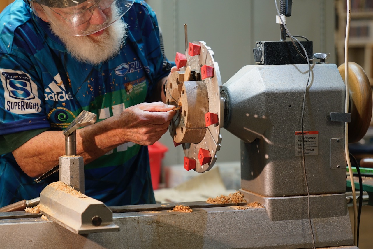
The vessel was then turned around and mounted on 100mm jaws in expansion mode. The hollowing was then repeated from the other side.
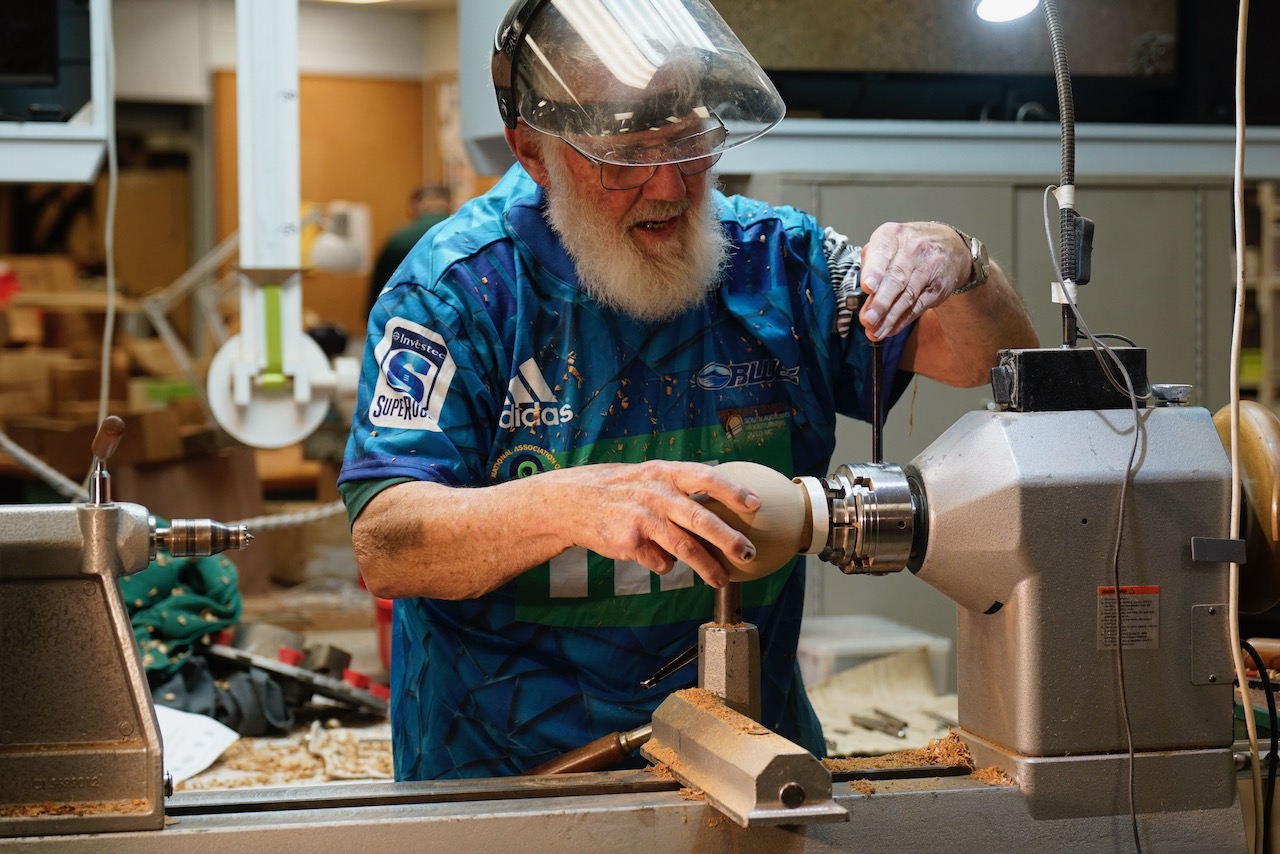
A Munro hollower was used to hollow under the rim.

Glenn then mixed powdered dye with isopropyl alcohol and rubbed in onto the vessel, using multiple coats to build it up to the desired colour.

Then Glenn moved onto making the disks to insert into the flask. He mounted the disk in the chuck and marked the size as measured from the recess. It was turned to size.


The insert was glued into the vessel, then the process was discussed further and it was determined that his normal process would have been to turn both disks before getting the glue out. (demo nerves)
He then drilled the hole for the spout to be put into
(Let us assume glue had not been used yet) The disks would then be smoothed to final shape, using the flash as a jam chuck. One side at a time with the other recess being used to mount the flask on the 100mm jaws.

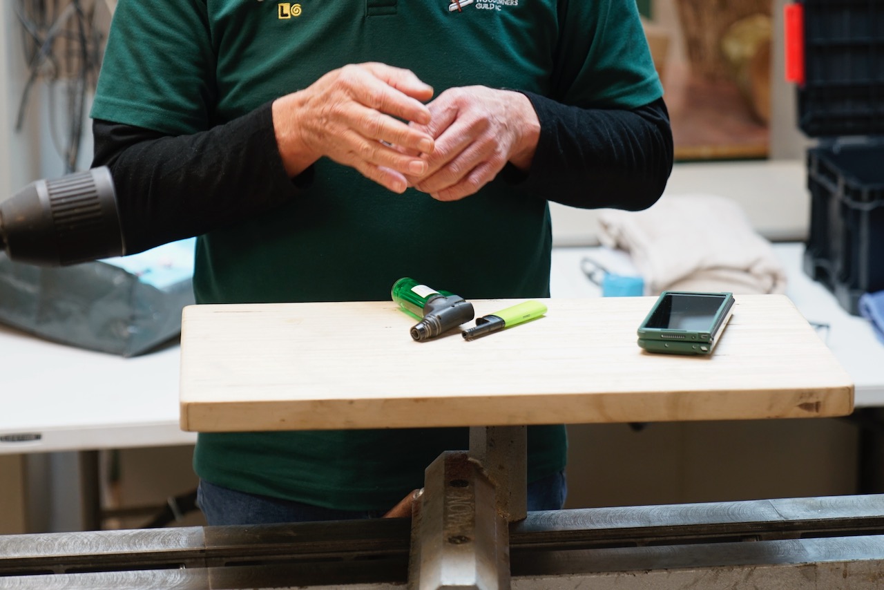
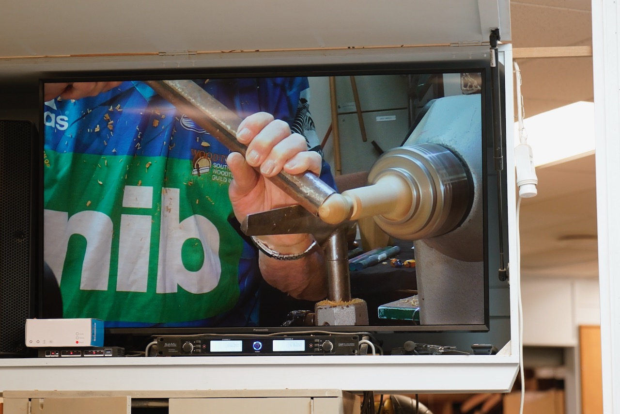
He then turned the spout and a stopper from a spindle blank.

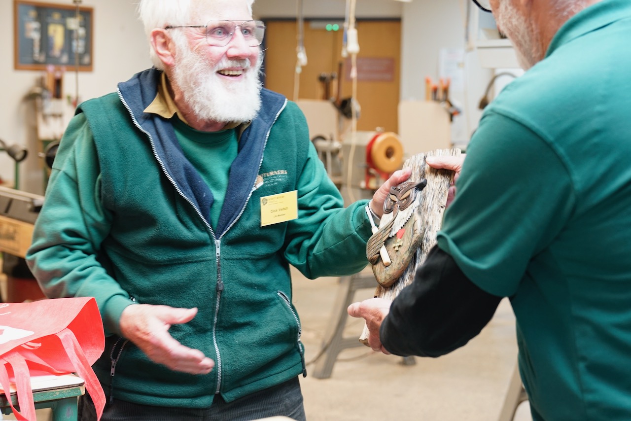
An entertaining demo, with techniques and inspiration for us all. Thanks Glenn.