Tag Archives: sticky

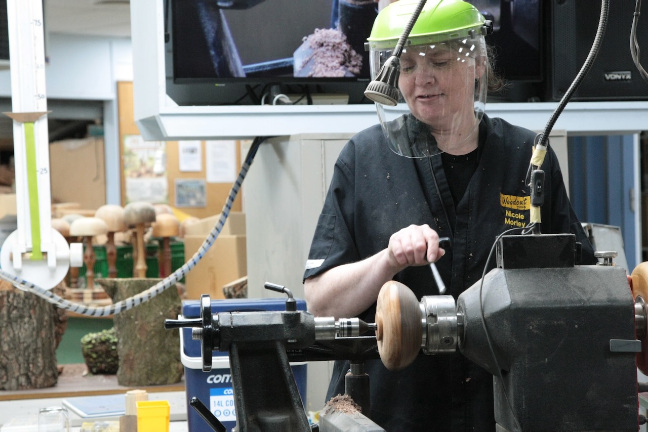
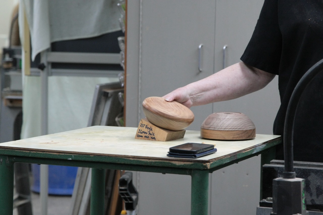
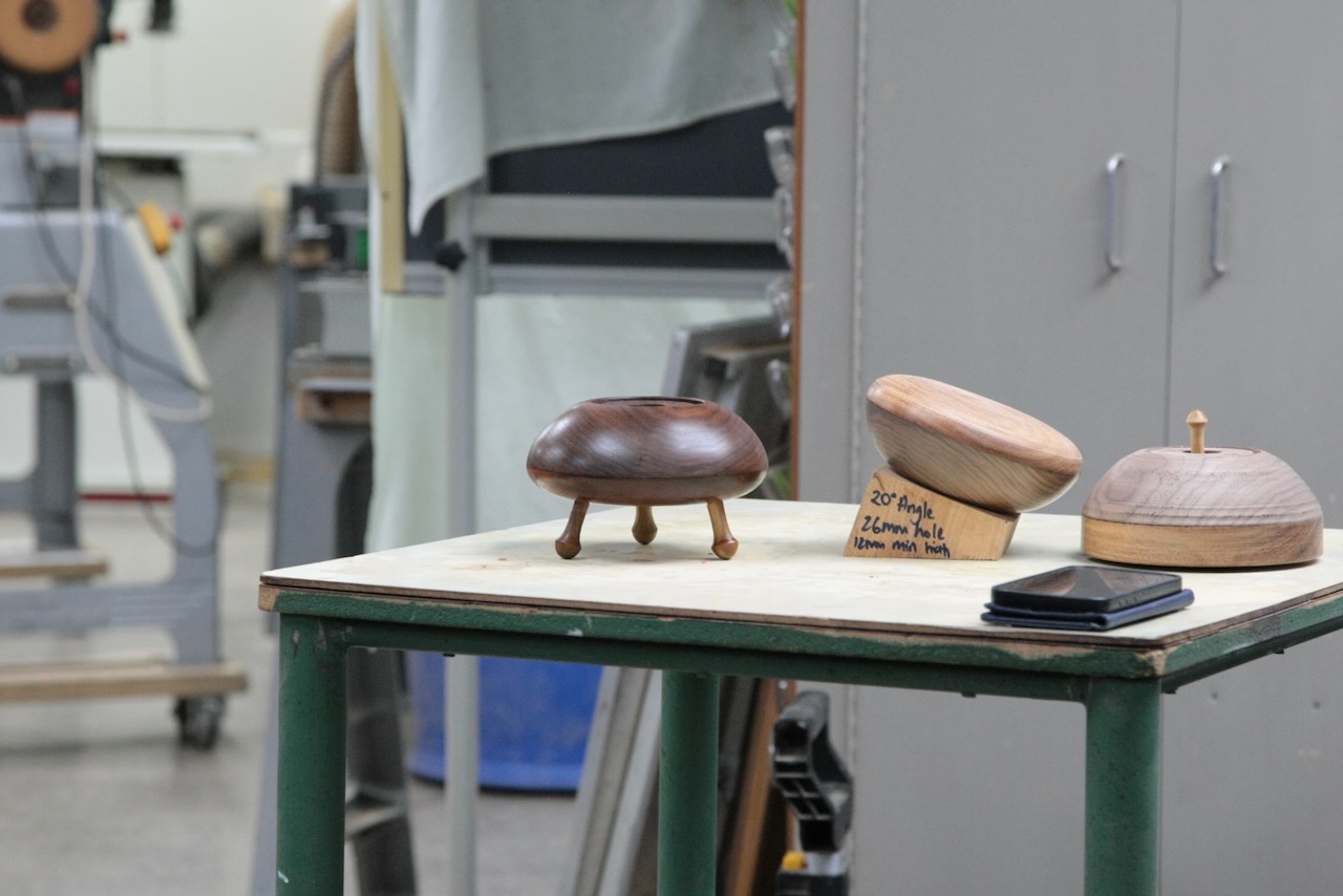
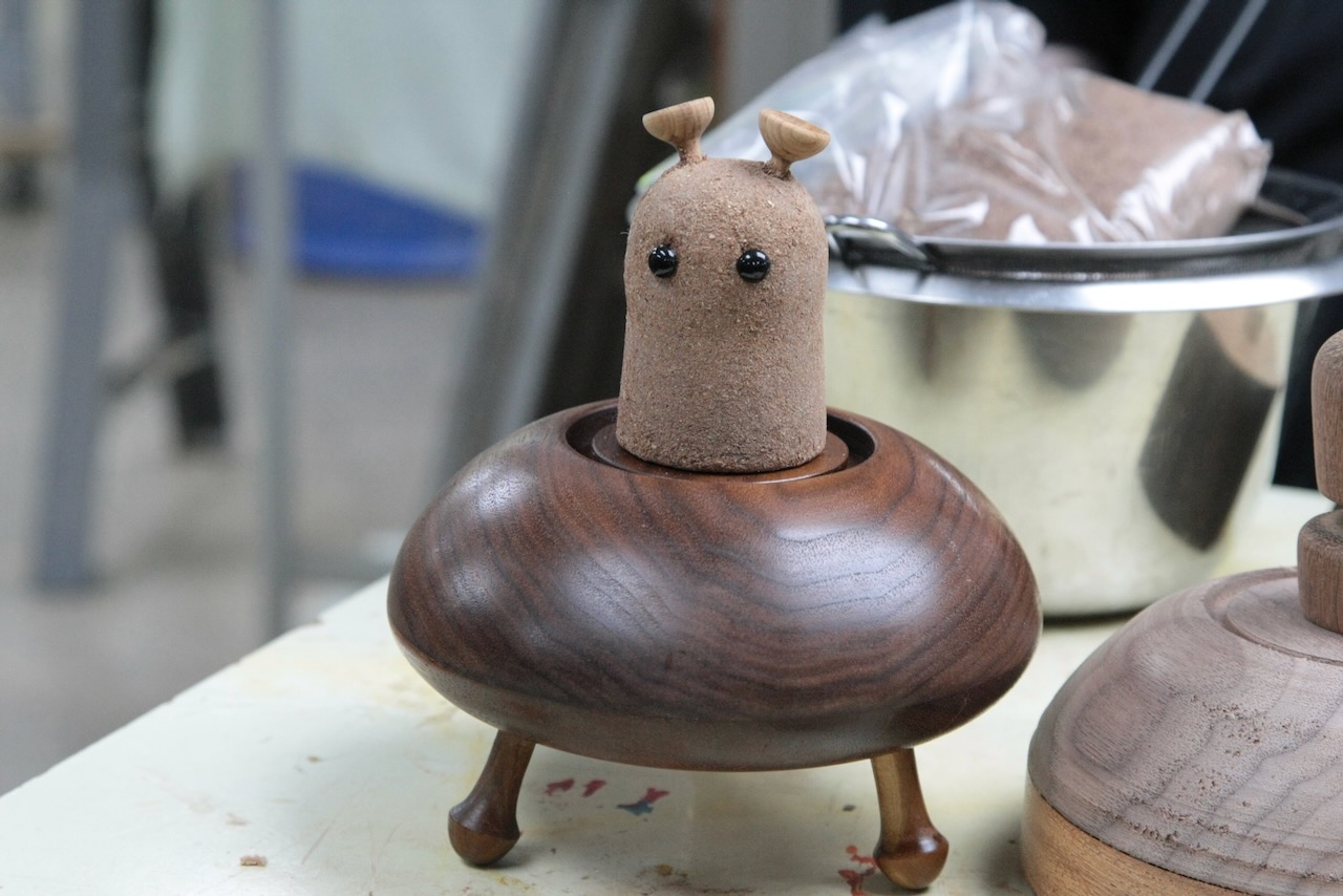
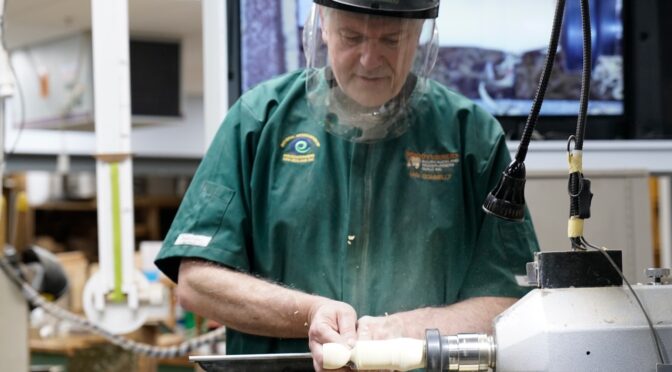
Ian Connelly – Offset/Wobble Chuck

Club Meeting: 19 August 2026
Report by: Jacqui Oxenbridge

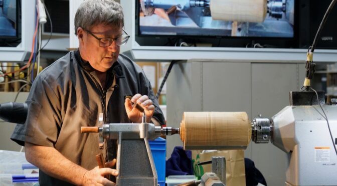
The journey all started at Turnfest this year with Len Mengel’s demo showing alternatives to wobble chucks.

Other inspiration came from Eli Avisera with his turned wine bottle and balance glasses and Radek Teterycz’s extreme turning where most of his work is done on the lathe – worth a look on Facebook or Instagram.

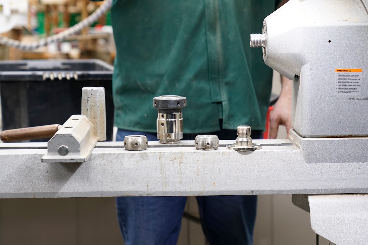
Part one of the demo will be showing the use of Colin’s Vicmarc Eccentric Chuck with a 40mm cup chuck and ball. He also has a separate ball (gimbal) that can attach to a Faceplate.
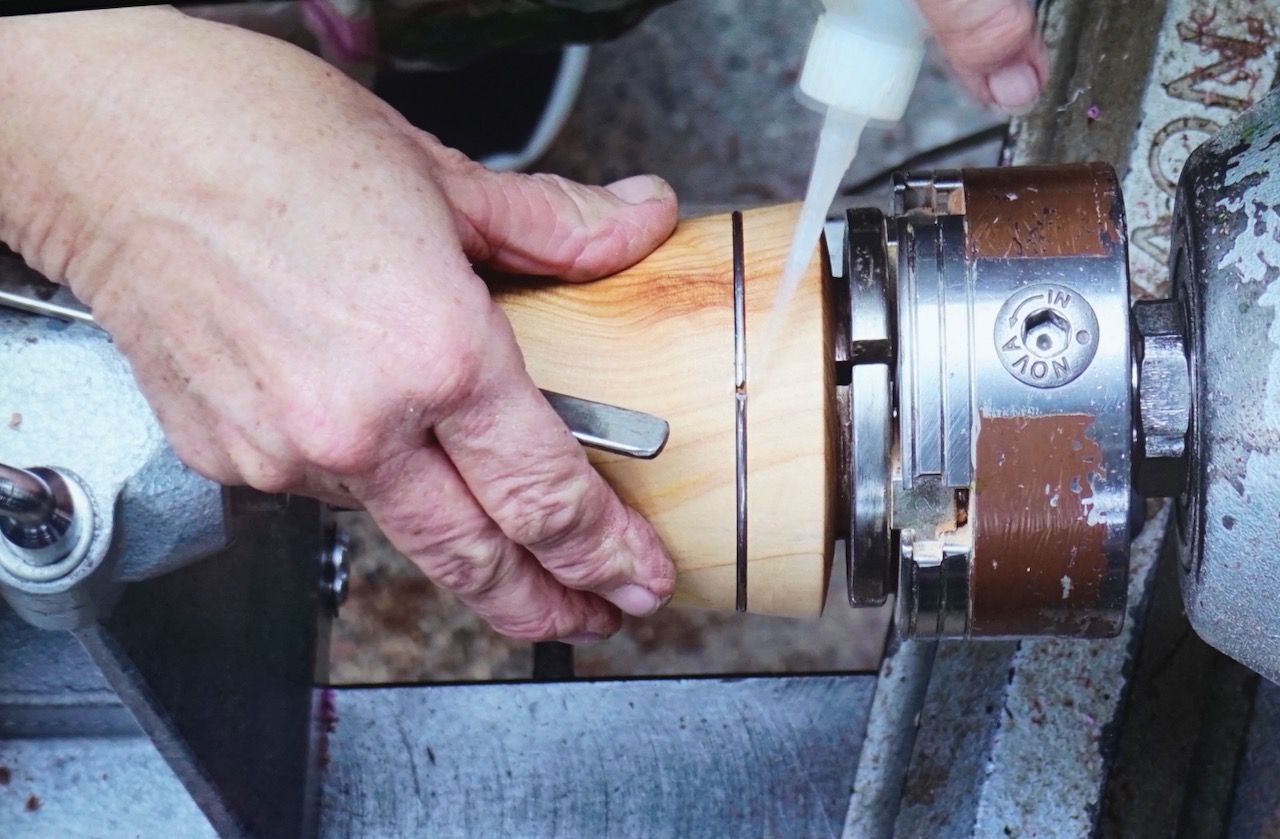
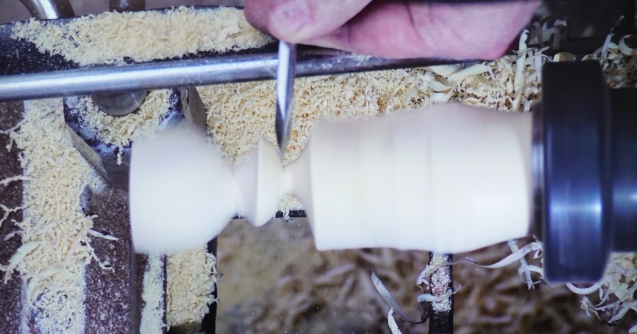
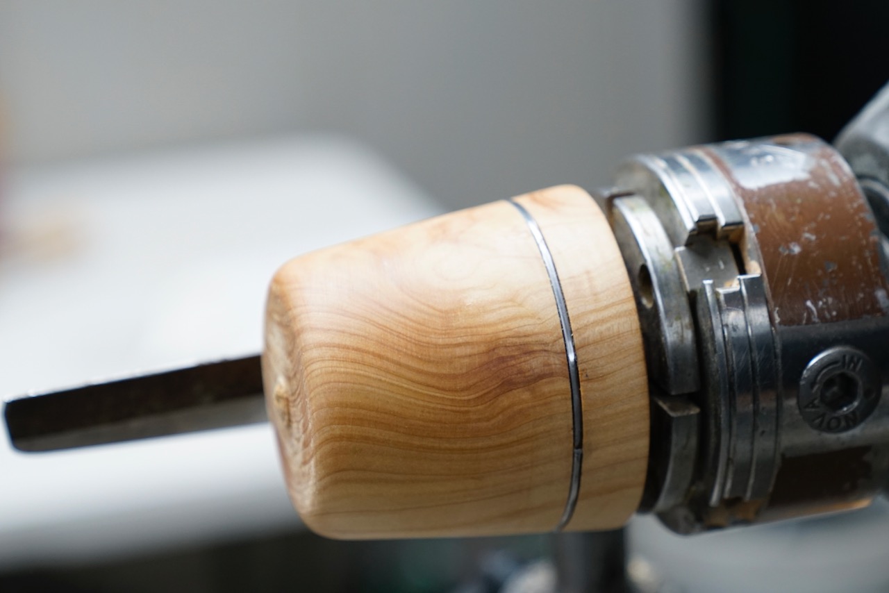
To use the “eccentric chuck” we first need to shape a taper that will fit in the ball/gimbal but not bottom out in the chuck. The gimbal can be moved inside the cup chuck when the appropriate grub screws are loosened off. Note: the blank is held in only by friction.

The chuck is a little confusing with multiple grub screws requiring different Allen keys. Some are marked with a line – these have a pin on the end which can go through corresponding holes in the ball to hold it in position when it is square (straight). The other grub screws are flat and tighten the chuck to the outside of the gimbal at various positions when turning off centre.
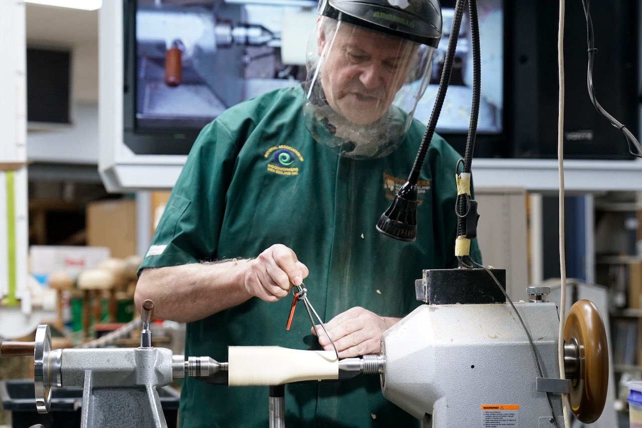
Place the blank between centres – using a smaller drive centre with a Steb live centre so if have a catch the mini drive centre point does less damage to the blank.
Round off the blank sufficiently that a taper can be made. To help ensure the taper is going into the ball/gimbal square, and how far in the taper has gone, can draw lines on the blank.

Push the taper in to the chuck/gimbal. If too large, turn more off the taper. Use a mallet to seat the blank tightly.

Tighten up the grub screws on the chuck to secure the gimbal.

Put the chuck on the lathe – note that the chuck has a dedicated thread.

Bring up the tailstock, begin to shape the blank.

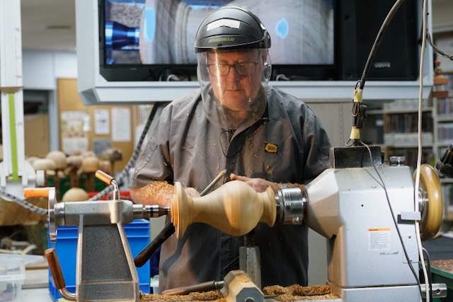
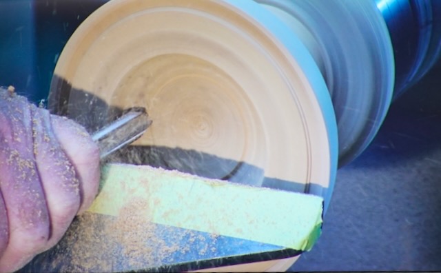
When the tailstock is removed to true up the end, and as you hollow the end grain with a spindle gouge to make the goblet REMEMBER to avoid aggressive cuts across the blank as it is relatively easy to pull the blank out of the chuck.

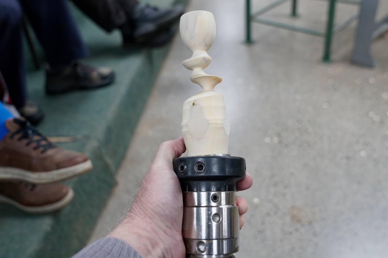
Once the goblet is hollowed, if desired, it is possible to use the tailstock in the hollow to stabilise the blank while cutting the outside shape of the goblet/stem/foot. Use a skew and spindle gouge to shape.

Ideally, you will know what shape you want to make before you start turning – it can be helpful to have a photo or drawing of your intended shape.

Once the goblet is complete, carefully sand and finish it as it is difficult to recentre the piece once you start off centre turning.

Now loosen off the screws on the chuck that are holding the gimbal in place so that the blank can be shifted. The movement is small and it is important to check that the base of the goblet is over the centre of the next section that will be turned. To check, move to where you think it should be, tighten 2 screws in the chuck to the gimbal and rotating the blank, draw a line to allow you to approximate where the centre will be. Once in the correct position tighten all the grub screws holding the gimbal in place.

Start to turn but before going too far, check the pencil mark again. There must be some of the pillar remaining to support the top cup. Adjust the position if required.

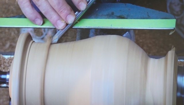
Working away from the goblet bring the next section into round. Use a spindle gouge and skew to remove surplus timber in the grooves. Once the desired shape is complete carefully sand this section only – do not attempt to sand the 1st goblet.

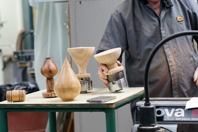
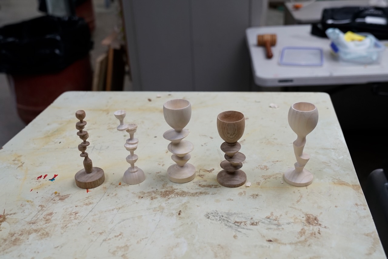
Repeat the process moving the blank, checking where centre is, turn the section – ideally keeping the diameter of each shape the same, sand.

Two things are important for success – your tools are very sharp and the timber has a straight grain and low tendency to split. Gingko was a good choice.

Sorby also have a Wobble Chuck which uses standard 50mm jaws. In this chuck the piece in the jaws rotates so changing the angle of the piece. The angle can be repeated so that less guesswork is required as to where to move the blank. This also has a worm screw to retain the work, or the screw can be removed and the faceplate attached to larger blanks.

Part two of the demo will be making stacked cups without a wobble chuck.

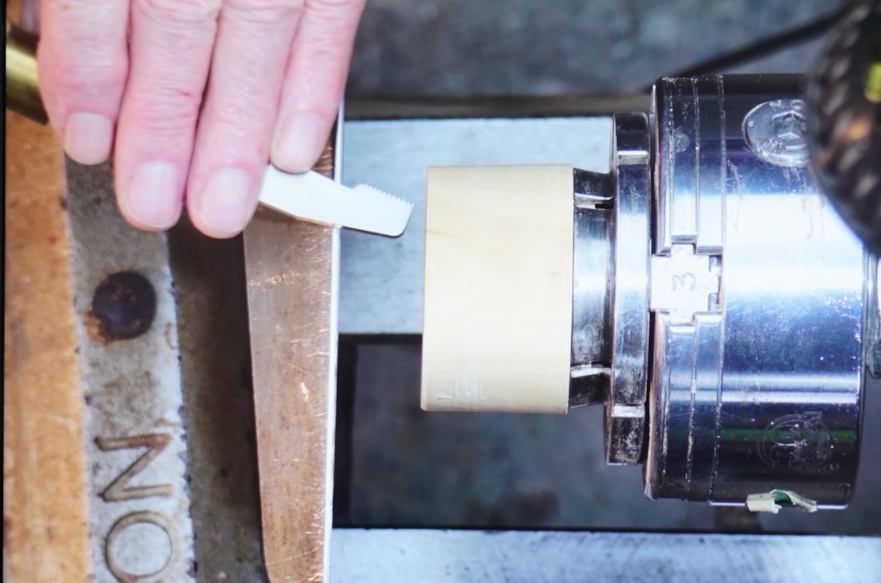
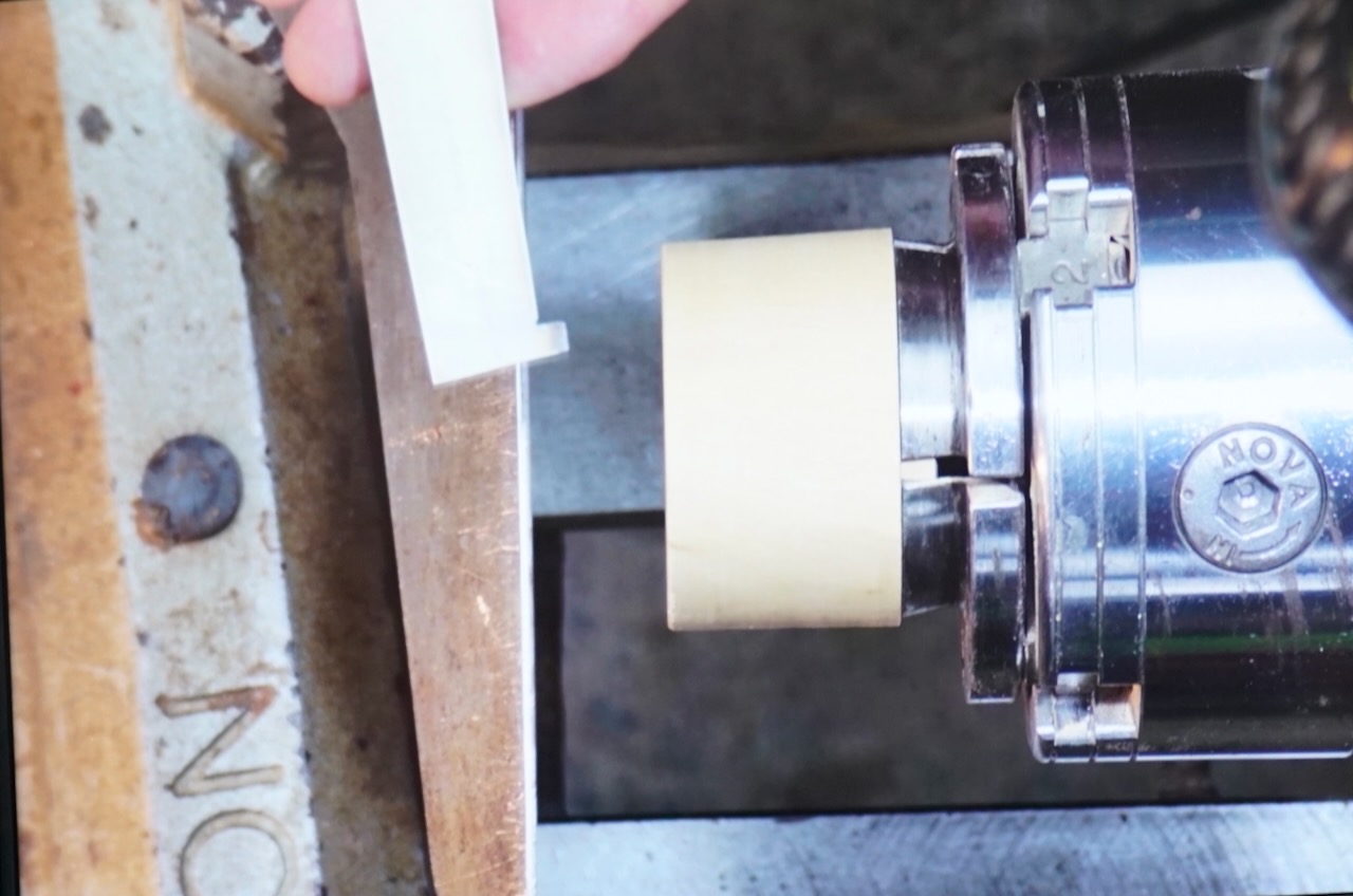
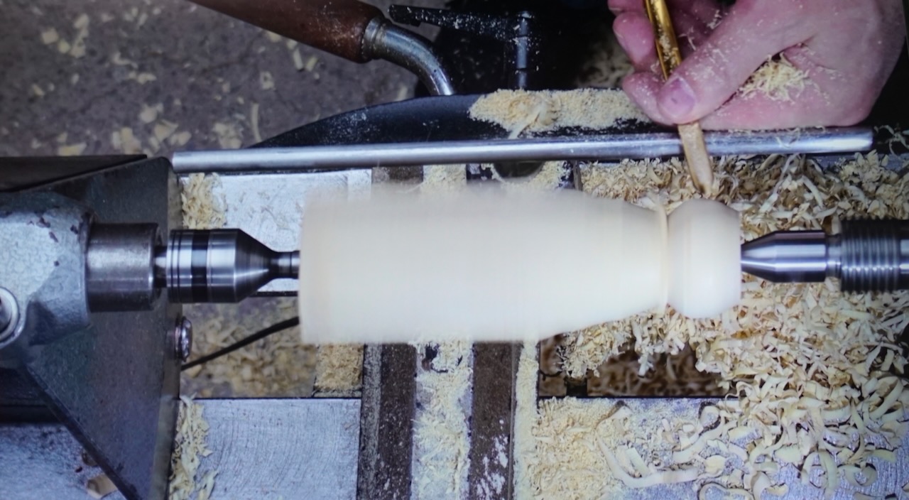
Mount the blank between centres, round off part of the blank. Turn a hemisphere (ball) on one end of the blank – this does not need to be super accurate but does have to have clearance so that it will fit into a set of jaws. For the demonstration used Nova 35mm spigot jaws with the serrated teeth for a powerful grip on the blank.

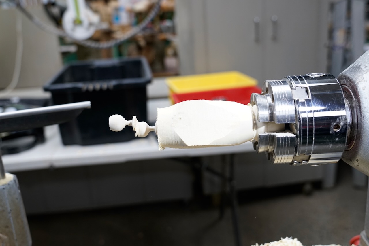
Put the turned ball into the spigot jaws. Can now adjust the position of the blank (ball and socket rotation).

The first time the blank is moved off centre it is possible to use the live centre in the tailstock to show where centre is to measure the offset. An alternative that could be use would be a laser pointer in the tailstock.

Start shaping the blank with a spindle gouge or for quicker bulk removal can use a skew or parting tool. Cut the length required for the first cup, continue until you get to the final diameter of the cup before start shaping the stem to avoid breaking the top off the cup! Once have shaped cup, stem and base – sand – very carefully.

Note: it is very important to have good light, contrasting colours on the lathe bed can be helpful.

Finish the top surface of the next section (closest to the headstock) before moving on to the next goblet.

Tilt the blank (tiny offset only). Where two “offsets” meet they will be angled at each other.

Use a pencil mark to work out approximately where centre is – needs to be under the existing cup. As with demo 1 – begin to cut but then check and reposition if necessary.

Tidy up the excess under the goblet foot with a skew or parting tool cutting in very carefully at an angle.

Aesthetically it is best to replicate the height of the goblets – could use a vernier to check.

Round off the same length tip to base as the first goblet then with a small spindle gouge or thin parting tool, shape the next goblet. Sand before changing the offset.

Repeat until you run out of blank, it breaks or you’ve got a piece you like!

Julie Gannaway – Filling Cracks & Inlay Techniques

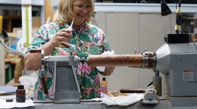
Club demonstration — Wednesday 12 August  |  Presenter: Julie Gannaway (North Shore Woodturners / NAW)

Overview

Julie ran through a range of simple, low-cost ways to fill cracks and voids and to add decorative inlay to turned pieces — from everyday coffee grounds through to metal powders, coloured micro-pigments, and inlaid wire. The session was explicitly framed as experimentation rather than a single “correct” method: several techniques shown had mixed results on the night, which Julie treated as useful material in its own right. Samples up to ten years old, including well-used cheese boards and outdoor pieces, were passed around to show how each technique holds up over time.

Materials & Tools

Material / ToolNotes
Ground coffeePerked coffee, ground extra fine on a second pass — cheap, dark brown, works with most timbers
Cyanoacrylate (super glue)Fast-curing; used to bind coffee, metal powders and wire; toxic fumes — ventilate and avoid sanding without a respirator
5-minute epoxySlower cure, doesn’t generate heat like super glue — better suited to heat-sensitive powders (e.g. aluminium) and bigger voids
Metal powdersBrass, aluminium, copper and turquoise (turquoise available in a couple of grit sizes plus a fine powder)
Micro/mica powdersFine-pigment powders (craft/hobby suppliers, e.g. Carbotex) in a wide colour range, used in pyrography or laser-engraved grooves
AcetoneKeep on hand as a safety item — releases super glue from skin/tools
Application toolsFine-tip applicator nozzles that come with super glue bottles; a cocktail stick or similar for working powder in (not fingers); insulin-style syringes for very fine, controlled super glue application; a small paintbrush for moving micro-powder
Wire (for wire inlay)Solder wire or copper wire, in a couple of thicknesses
Parting tool(s)Sized to match the wire thickness being inlaid

General Safety Notes

  • Super glue fumes are toxic — work with adequate ventilation.
  • Wear a respirator when sanding filled/inlaid pieces, particularly with metal powders.
  • Use a stick or similar tool to work powder into glue — not fingers, both to avoid gluing yourself and due to toxicity.
  • Keep acetone close by to free glued fingers/tools if needed.
  • Seal the surrounding wood before applying super glue — unsealed grain will wick the glue and leave visible stain lines.

Technique 1 — Filling Cracks with Coffee

  1. Seal the wood around the crack first — unsealed super glue will stain and telegraph through the surrounding grain.
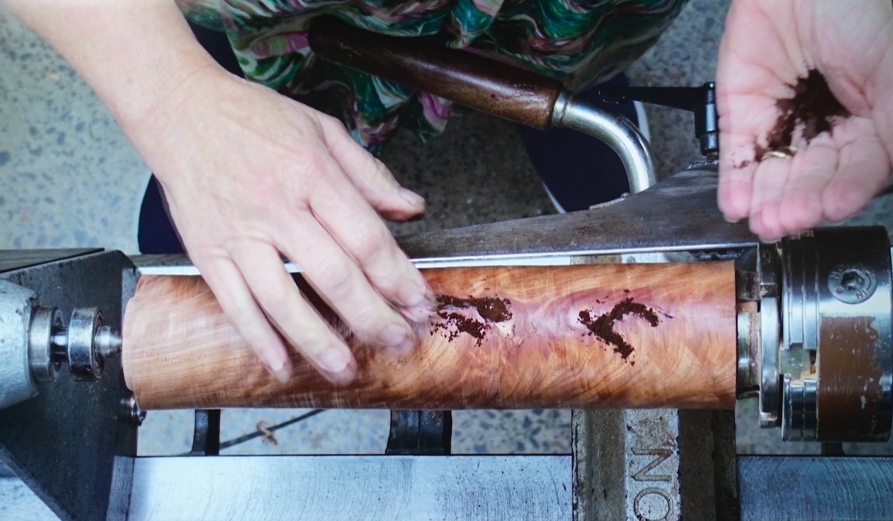
  2. Use finely ground coffee (perked coffee, run back through the grinder for an extra-fine grind). The dark brown tone suits most timbers.
  3. Pack coffee grounds into the crack, then apply thin cyanoacrylate (super glue) through a fine applicator tip, letting it wick down into the grounds.
  4. For bigger voids, pack with sawdust first, then coffee on top — coffee is cheap enough to use generously regardless.
  5. Avoid accelerator sprays where possible — they can trap voids under the surface that only show up once you turn back into the fill.
  6. Once cured, rub over with a finger — this grinds the coffee finer still and helps you feel out any remaining fine cracks.

Black-tinted super glue (available from club suppliers) is a simpler alternative to coffee on dark timbers and can read as natural grain. On lighter woods the coffee’s brown tone was generally preferred.

Longevity: samples shown included a cheese board with a ten-year-old coffee-filled crack, still sound after years of use and washing — provided the filled area isn’t load-bearing/structural, as timber movement can eventually reopen a crack regardless of fill.

Technique 2 — Metal Powder Inlay

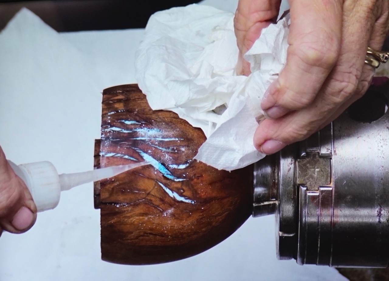
  1. Available powders: brass, aluminium, copper, and turquoise (turquoise comes in a coarser grit and a fine powder — grit can be used first to fill bulk, with powder used to fill remaining gaps).
  2. Applied the same way as the coffee technique — pack the powder, then feed in thin super glue.
  3. Apply in thin layers rather than all at once. Powder applied too thickly can leave a hardened surface film with loose, uncured powder still trapped underneath.
  4. Caution with aluminium and pewter powders specifically: cyanoacrylate curing generates heat, and can exceed the melting point of these metals, leaving a dull, oxidised finish instead of a bright metallic one. Five-minute epoxy (which doesn’t generate heat) is a better binder for these two powders.
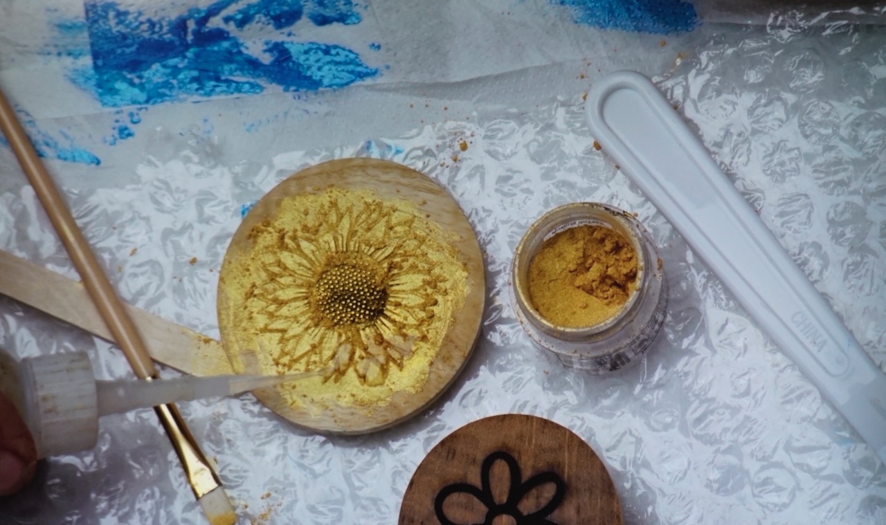
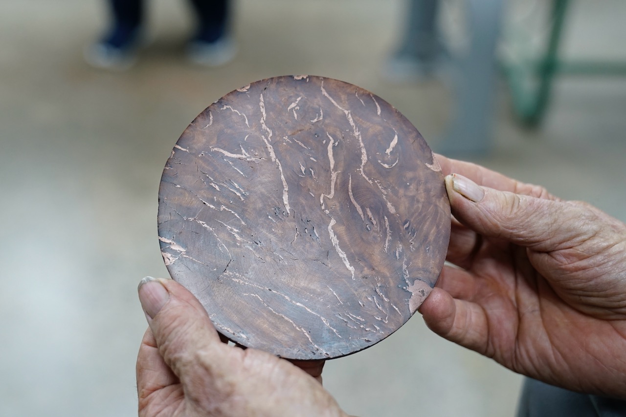
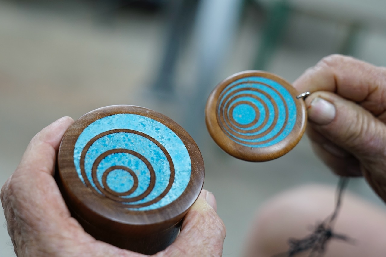
  5. Copper and turquoise powders were shown as reliable, attractive fillers for burl voids and fissures — examples included a filled burl disc used as an inset panel and a decorative box lid using mixed turquoise grits.

Technique 3 — Micro-Powder (Mica) Inlay in Engraved Grooves

  1. Cut fine decorative grooves using pyrography, or have a pattern cut with a laser engraver (settings — speed, heat, power — need adjusting per timber species).
  2. Fill grooves with coloured micro/mica powder (a wide colour range is available from craft/hobby suppliers).
  3. Bind with either super glue or 5-minute epoxy — both were demonstrated side by side for comparison. Epoxy was found generally easier to control and better suited to larger fills; super glue suited smaller, finer work.
  4. A small paintbrush is useful for moving and placing micro-powder precisely, since it’s very fine and prone to going everywhere.
  5. For very controlled, fine application of super glue (rather than a full applicator-tip stream), an insulin-style syringe gives much finer, drop-by-drop control — useful for filling narrow grooves one ring/section at a time without overflow.
  6. Where a design has multiple colour zones, mask off completed sections before adding the next colour, or work from the centre outward, to avoid muddying colours together.
  7. Once cured, sand back carefully — excess glue/epoxy on the surface cleans up easily, but avoid sanding through the full depth of shallow grooves.

Julie noted this technique is still a work in progress in her own practice — several samples shown had inconsistent results (air bubbles in epoxy fills, colours bleeding between sections), included deliberately to show realistic outcomes rather than only best-case results.

Technique 4 — Wire Inlay

  1. Select wire (solder wire or copper wire both work; two thicknesses were shown).
  2. Measure the wire’s thickness — this determines the groove size needed. Cut the groove slightly bigger and deeper than seems necessary, as it typically needs to be more generous than expected.
  3. Cut the groove using a parting tool sized to suit — have a couple of parting tools of different widths on hand to match different wire gauges.
  4. Seal the wood before gluing (as with the other techniques).
  5. Lay the wire into the groove with super glue, working it in with patience — the first section takes a moment to tack down, after which the rest follows more easily.
  6. Once glued, peen/hammer the wire to spread and flatten it into the groove, fully filling the channel; a smooth file can also be used instead of a hammer for a flatter, more finished face.
  7. Trim any excess length once secure, then true up on the lathe.

Durability: Julie’s original outdoor coffee table inlay pieces lasted roughly eight years outside before the surrounding timber eventually cracked — notably, the wire itself stayed firmly in place the entire time.

Variations mentioned: twisted wire (by hand or with a drill for a tighter, more even twist) for a decorative pattern; aluminium powder can be used to dress/fill a slightly proud joint in the wire before final finishing.

Closing Notes

  • None of these techniques are presented as the only or “correct” way — Julie encouraged experimenting and adapting them to individual style and the piece at hand.
  • Keep a small dedicated box of filling/inlay supplies near the lathe so a crack encountered mid-turning can be dealt with immediately rather than becoming a separate trip/session.
  • Bringing imperfect or “failed” examples to a demo was called out as valuable — seeing what goes wrong is as instructive as seeing a finished piece.

Dick Veitch – Santa Claus is coming to Town

Club Meeting: 5th August 2026
Report by: Matthew Brown

There was a good turnout at the club to see what our resident Kris Kringle was going to demonstrate. With a little model Santa Claus placed at the end of the presentation table, plus a box of secrets, Dick started the demonstration.

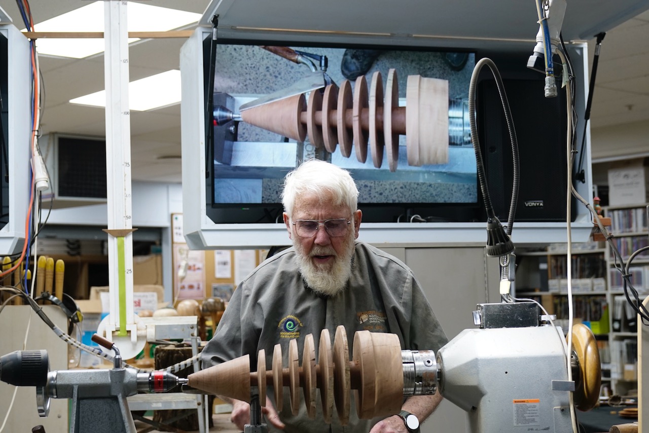
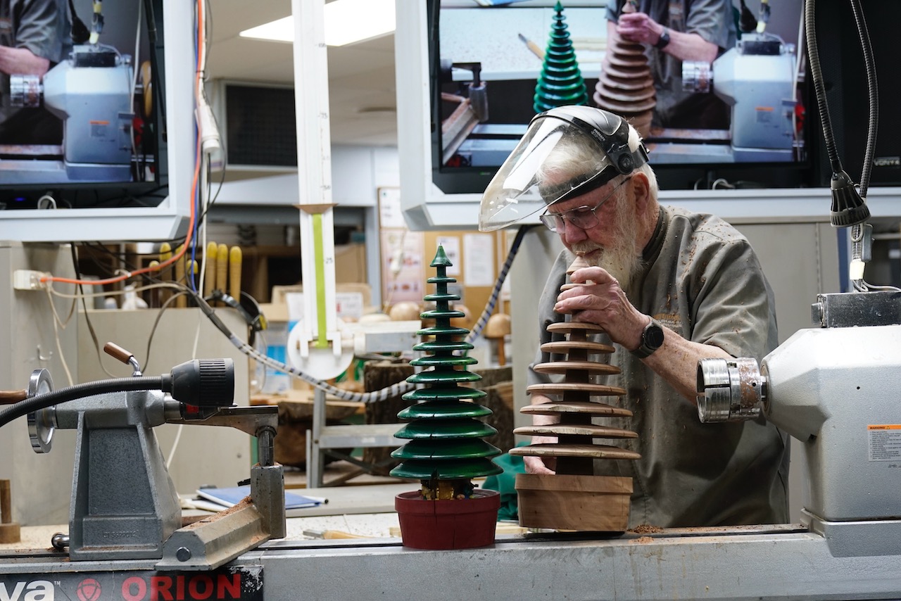
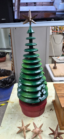
He revealed his 70% pre-turned Christmas tree made of pohutukawa. Approximately 400+-mm x 250mm at the base in size, he commented this wood was particularly hard, and it had given him a good work-out of about 5 hours to get it to this level. The Christmas tree already had it’s base, plus 6 of the branches leaving just the cone at the top awaiting its last few layers. 

He mounted the base into a 100mm chuck and into a live centre in the tailstock. Using a parting tool and starting at approximately 800 RPM, increasing the speed once he had confirmed it was stable. 

Note the central trunk of the tree reduces in diameter with each layer as it nears the tip of the tree. He angled the parting tool rather than cutting straight in at 90 degrees to create a chamfered effect to each individual branch layer.

He turned an additional 3 layers of branches using the parting tool, but the top was turned to a fine tip using a bowl gouge, but leaving the recess in the tip. Using the same gouge, he rounded over the rims of the individual layers, adding to the effect. 

Remembering back to our Blue Peter watching days, Dick pulled the classic “here’s one I made earlier” move as a finished example was brought out on display. It was complete with 2 tone spray-painted green branches, a red base and what looked like presents and elves under the tree, it even had fairy lights too! 

Making an 8 Pointed Star:

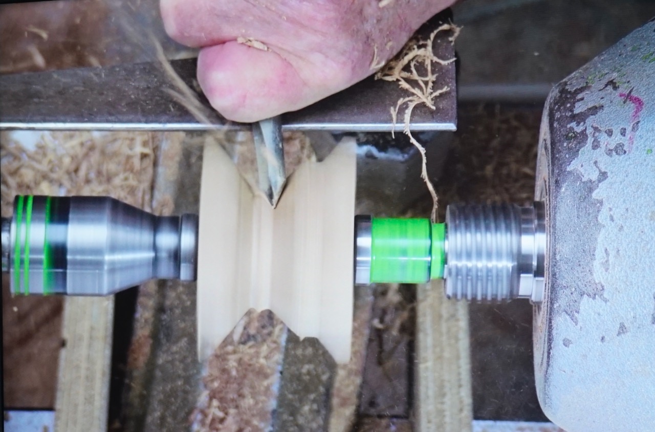
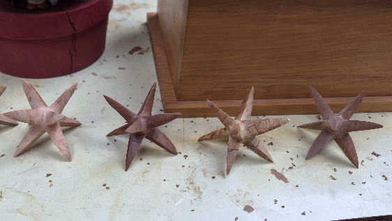
Dick took out a 50mm cube and marked it as precisely as he could, the centres and mounted it on a spur drive and used a Sorby drive steb centre on the tail stock using the pre-marked holes. The plan is to create a V shaped cut, dead in the centre of the cube, leaving an approx 22mm shaft. Accuracy is crucial so Dick brought out a handy clipboard/bookrest type of jig with a V printed to scale on a piece of paper that was positioned behind the piece. He positioned it directly in his line of sight as a reference point as he turned the V shape using a spindle gouge at 2000rpm. When asked by Terry, Dick advised that it didn’t really matter if you turned it end grain or cross grain first.

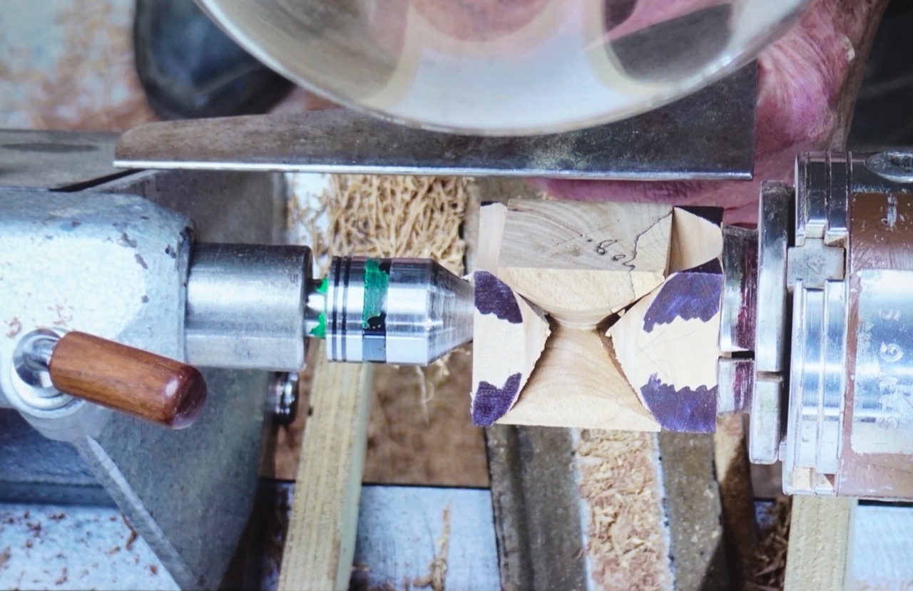
Once the first V was completed you could see a rudimentary 4 points, now the trick to make the other 4.

Dick showed us that he had brought 2 pieces of timber that had convex shapes sanded into the ends of each piece, that mached the V shape cut in the cube. The cube was turned 90 degrees on its axis, and held firmly between the centres by the aforementioned drive blocks, and the next V was turned again being careful to maintain the same centre and depth of the V as the first one. Once that was done, rotate the axis once again and repeat the V cut to create the last points of the star.

The accuracy of marking the centres and maintaining the same depth of the V’s became more apparent when turning the last V cut in the 3rd axis as a few tips of the star were lost as they became finer and more delicate. Once again, Dick produced another “here’s some I made earlier” moment from his “magic box,” presenting multiple stars for our inspection.

One of the stars took pride of place, mounted at the top of the Christmas tree in the recess left in the tip.

Another great demonstration, thank you Dick, and there’s plenty of time for everyone to get practising for Christmas!

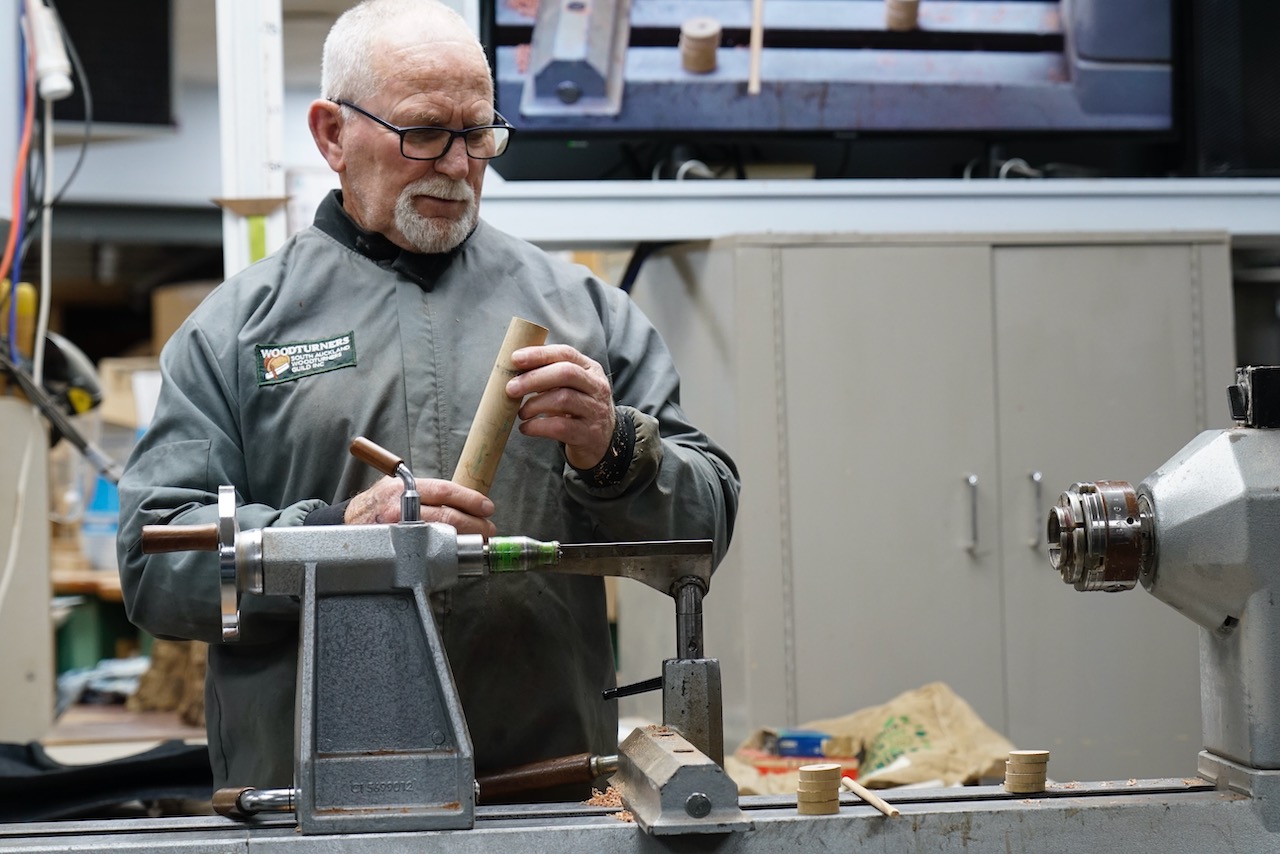
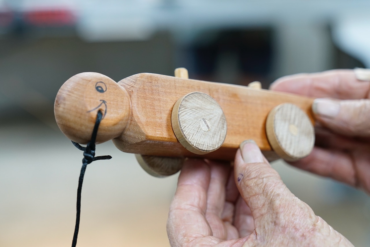
Gary Jones – Turning a Tow Along Turtle

Club Meeting: 29th July 2026
Report by: Jacqui Oxenbridge

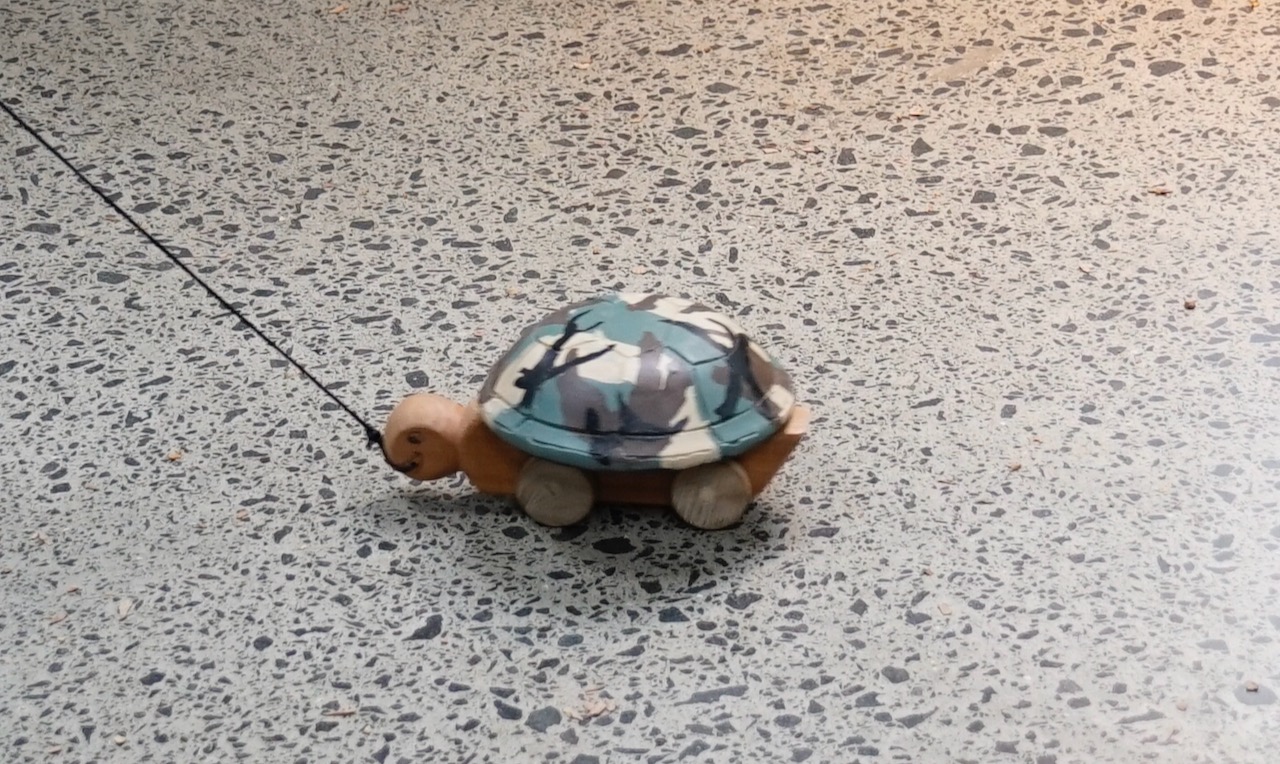
I’m not sure there is much value in doing a report as the project sheet is very comprehensive, but here it is.
Project Plan: https://sawg.org.nz/sawg/wp-content/uploads/2023/04/Turtle.pdf

Requirements:

150 x 150 x 40mm blank for the shell

40 x 30 x 200mm blank for the body

50 x 50 x 100mm blank for the wheels (or cheat and get 40mm dowel)

Making the body:

The height of the turtle body is 40mm, width 30mm and length approximately 200mm but if your blank is a bit shorter you can adjust the length of the tail.

Mark the centre on one end of the body blank, the other end will go in a chuck.

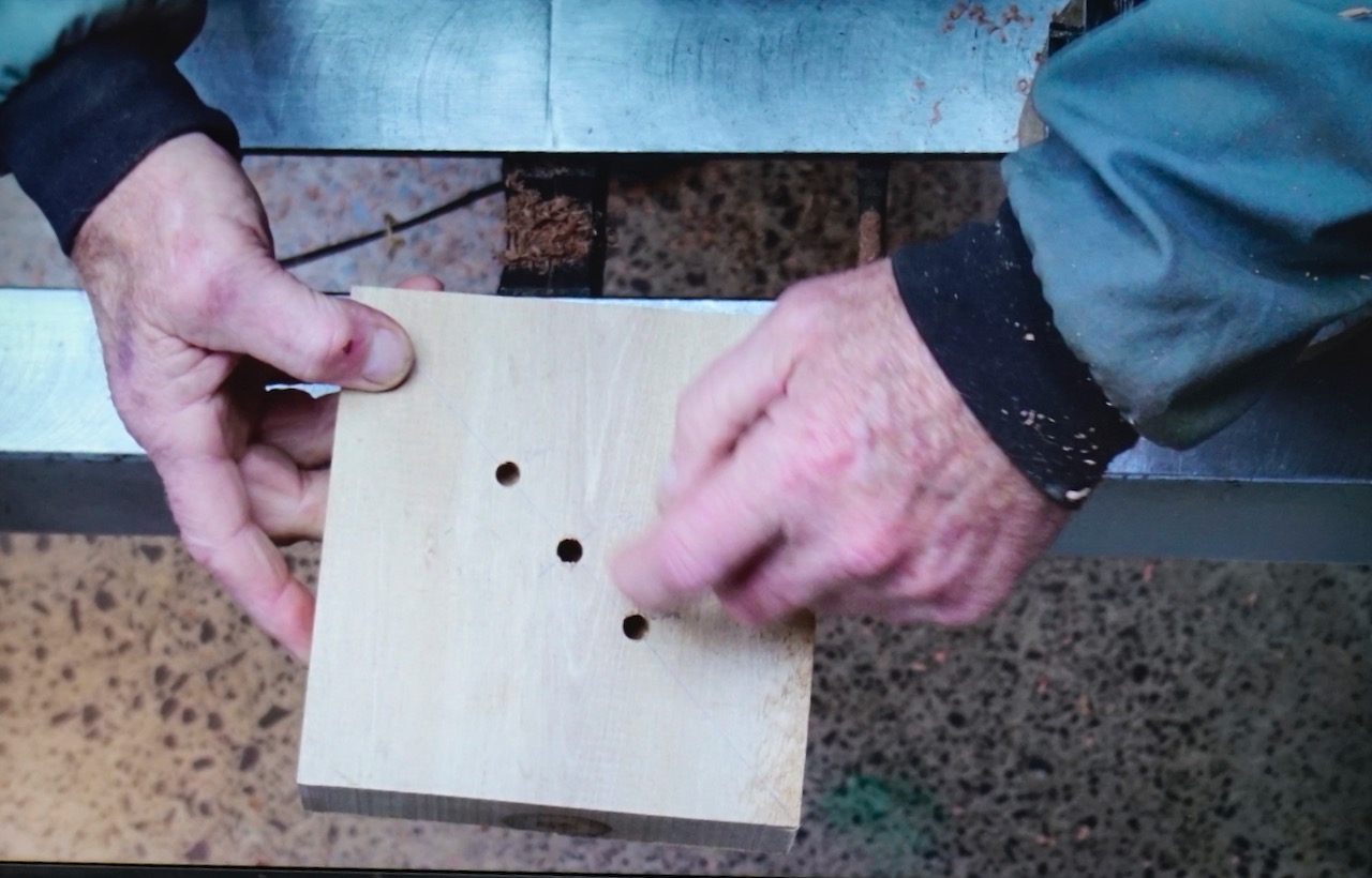
Using a drill press (or guide to ensure your holes are vertical) drill two 8mm holes in the centre line of the top of the body (that is the 30mm width) for the dowels that will hold the shell. These should be at least 10mm deep. Position the first hole 50mm from the tail end and the second a further 60mm in (110mm from the tail end) – see project sheet.

Now drill two 9mm holes for the axles. These are on the side of the body 45mm from the tail end then add 70mm to the next hole (115mm from the tail end). The holes should be centred at 10mm from the base – see project sheet.

Now mount the tail end in the chuck. Bring the tailstock up to the centre mark on the head end, tighten the chuck and turn the head round – leaving the sides flat for the eyes, mouth and to put the pull cord through. Turn the shoulders. Remove the tailstock to finish shaping the head. Paint or draw on the eyes and mouth and drill a hole for the string. This is towards the front of the base of the head – see project sheet.

Use a bandsaw or Japanese saw to shape the tail.

Push the 8mm dowel into the two holes on top of the body and cut off approximately 10mm above the body to attach the shell. Add the pull string and secure (important that no parts can come off for a child to swallow).

Wheels:

Either use the 50mm x 50mm blank and turn it round or use the 40mm dowel. Mount in a chuck (turn a spigot if using square blank) and dress the end of the wood then sand. Bring up the tail stock and part off an 18mm wide wheel. Sand the parting on both sides. Repeat three more times.

Note: if you want to add “tyre treads” using an embellishing tool, this should be done before parting the wheels.

Mark the centre on each wheel (if using red Nova centre finder, use the 45o side as 90o side doesn’t work). Now offset each hole by a couple of mm so the turtle will wobble as pulled along – see project sheet. Using the drill press drill an 8mm hole through the offset point at 90o angle. Sand. Paint if desired. Put axle through the body and glue on the wheels at each end.

Shell:

Find the centre of the blank. Mark a diagonal line through the centre and mark 30mm either side of the centre for the dowels. 

Drill an 8.5mm hole in the centre for a screw chuck. Drill 8mm holes for the dowels to hold the shell to the body.

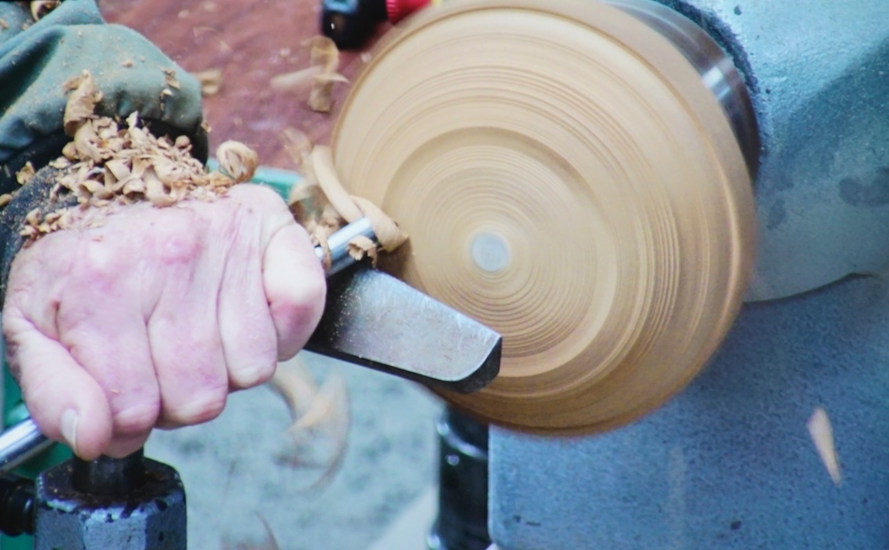
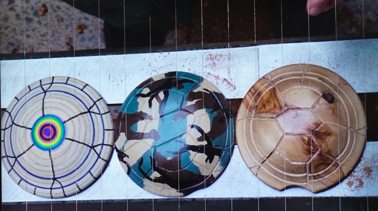
Round the blank, turn into a flying saucer shape. Undercut slightly. If you wish you can remove a portion of the edge (in line with the dowel holes) so that the shell sits nicely over the head. Sand. Now the shell is ready to draw, carve or pyro a turtle pattern on top (can get a pattern from Pinterest). 

Put the shell on to the dowels and once happy with it, glue the dowels into the shell and the body.

Bryan Mawhinney – Adaptations on a Simple Pen

Club Meeting:  22 July 2026
Report by:  Kieran FitzGerald

On a cold winters evening, on a train bound for nowhere, I met up with   ……  oops, wrong song.

On a cold winters evening, too cold for the two Jims, the Ngatea bus trundled into Papatoetoe and unbundled its scruffy load.  No gun totin’ gamblers these, just hard livin’ turners from the hinterland folks call the Hauraki Plains, a low lying flat countryside where the fog nourishes everything and the sun struggles to send its rays to the cold earth.  

Bryan steps down from the bus, hefts his toolbox from the boot and carries it into the clubrooms. The audience waits in wonderment and anticipation, because although Bryan is listed as the demonstrator for the evening, he has not disclosed what he is about to do.  “It’ll be an easy cleanup” he announces.  For Bryan is going to demonstrate the project called “Simple Pen” on the SAWG project pages.  But wait, there’s more – for Bryan will add some novel and creative features to improve the basic pen.  Lets get under way.

Some informal chatter preceded the demo, as members discussed the use of pens in the visitors packs, pens as complementary gifts, the origins of the pen tradition, and the tricks played on former member Rex H.  The casual talk set the tone for a boisterous and fun demonstration.

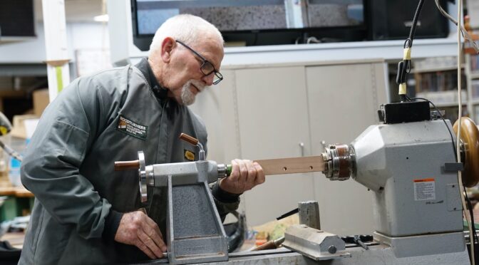
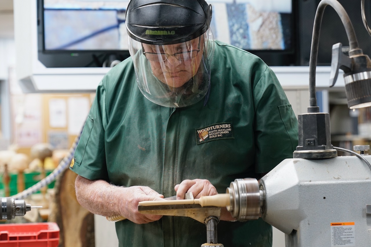
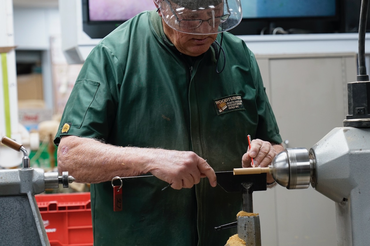
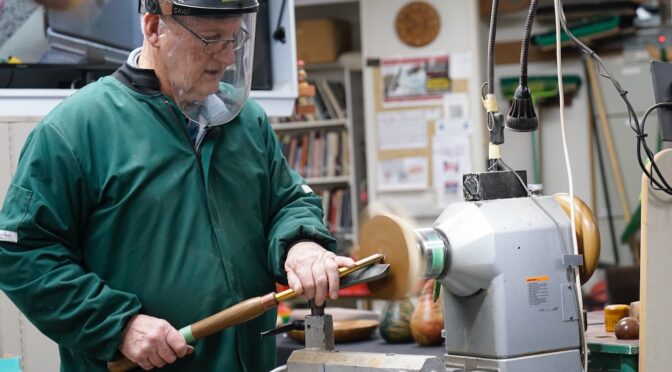
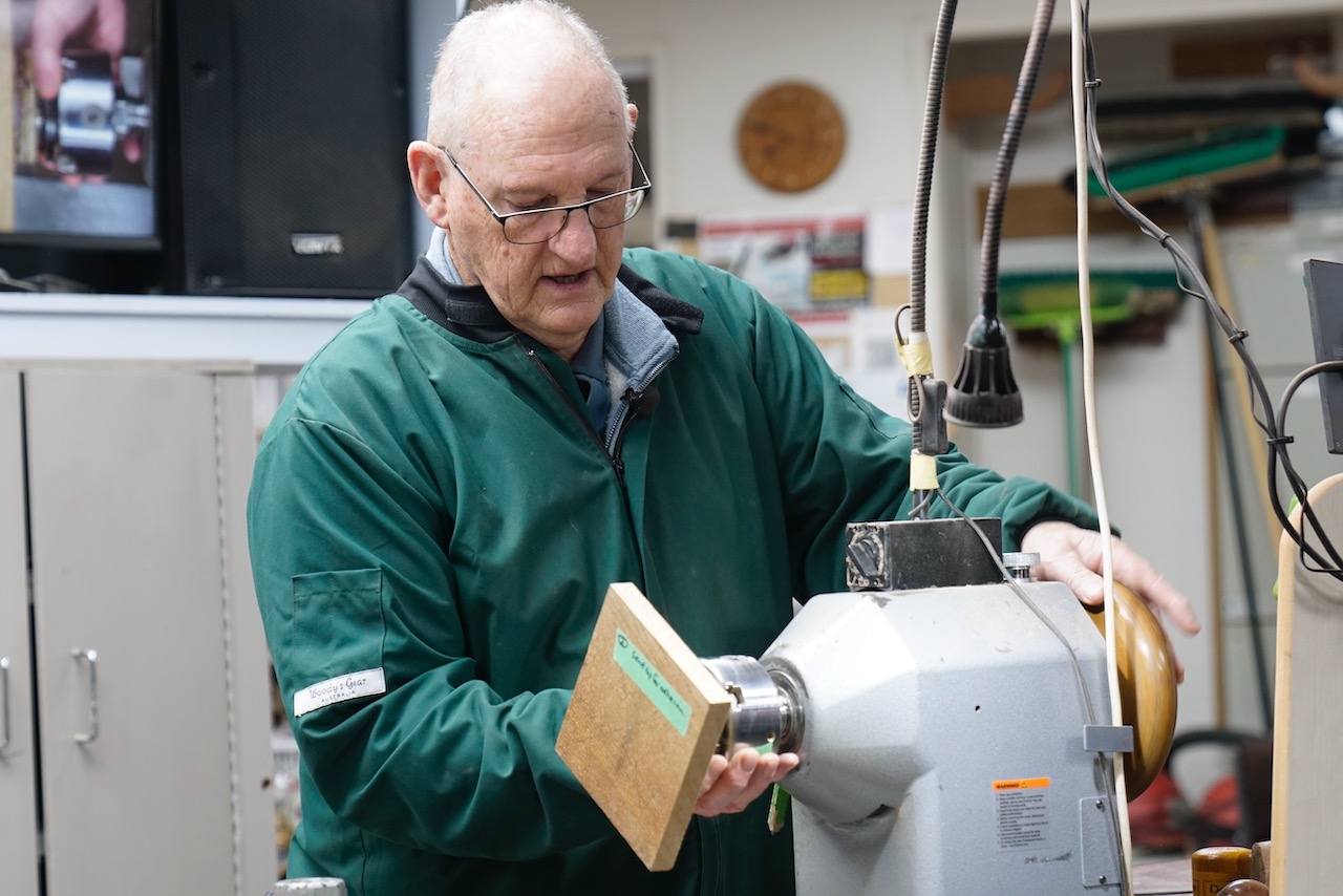
Bryan started with a blank which looked to be about 20 x 20 x 220.  Just guessing here.  It was slim enough to be held securely in the centre of a 50mm chuck.  Bryan brought up the tailstock and knocked the corners off the blank with a spindle roughing gouge.  He jacked up the speed and rounded it down to near finished size with a skew.  The length of the pen will be approx. the length of the refill plus about 10mm.  Without turning off the lathe he turned the speed down to about 1500 and gently withdrew the tailstock.  It is important that the piece continues to run true.

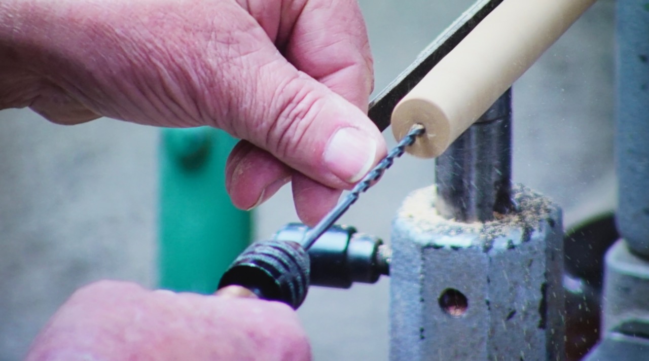
The next step is the tricky part and the key to a successful pen.  With a long series 3.5mm handled drill make a hole down the length of the blank which is slightly longer than the refill.  About 130mm should do it.  The drill will be very inclined to wander off centre as it follows the grain of the wood, so hold it parallel to the bed and on centre, and push it gently in just a few mm at a time before withdrawing to remove the swarf.  Doing it by hand is easier and more successful than using a Jacobs chuck.  Then drill a 4mm hole into the first 10mm of the wood to accommodate the shoulder just beyond the nib of the refill.  This will hold the refill securely.

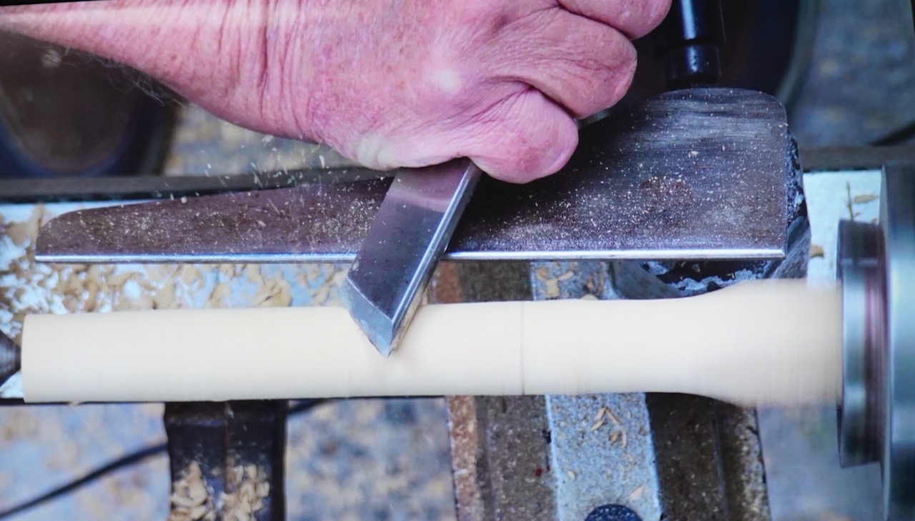
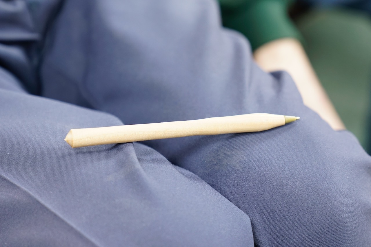
To complete the turning, Bryan took a 4mm drill bit and put it into the Jacobs chuck backwards, and brought up the tailstock again.  The drill bit slots into the hole and holds the blank nicely. (An alternative is to use a 4mm pop rivet as described on the project page, but Bryan reckons his way is better.)  Turn the pen down to its finished shape, sand and part off.  Insert the refill, put a finish on, and that’s your job done.  But here’s where Bryan added extra oomph by showing us several ways of enhancing the concept of a simple pen.  These certainly raised the bar.

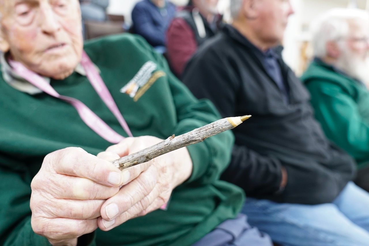
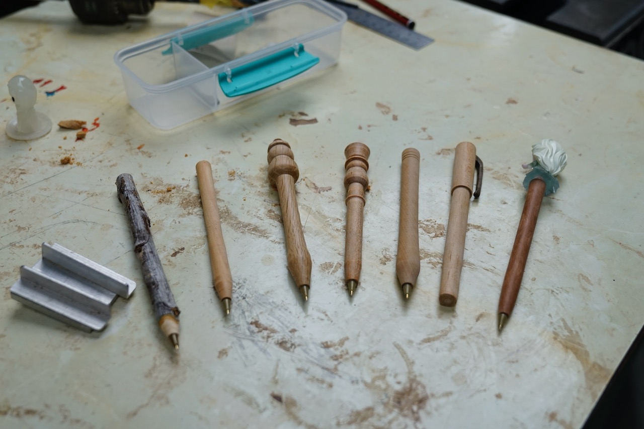
First off, he passed around several pens which he had previously made, and these were totally original.  Number 1 was a pen made from a small branch of apricot tree and it still had all the bark and growth nodes.  It was very cool.  Next up was a figure of a man with a hat turned into the end of the pen, and painted.  Anyone would love that.  There were a few pens with different designs turned on the end, and even a pen with a Woolworths giveaway figure on the end.  Bryan was very excited about that one. “It was free!”

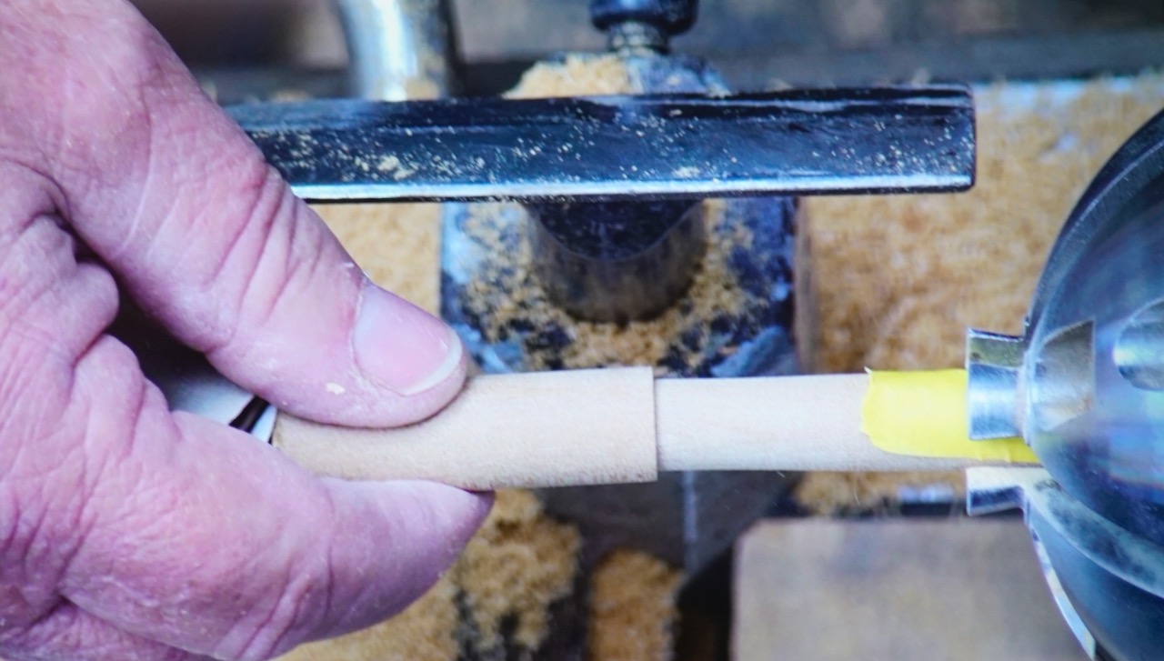
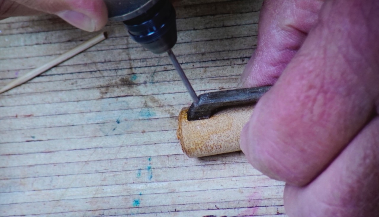
To cap it off (note the pun), Bryan demonstrated how to turn a cap for the pen he had turned.  Taking the parted offcut, Bryan turned it around and slotted it in the chuck.  He made an entry hole in the end with a gouge, and then drilled in about 40mm with an 11.5mm drill (use a drill sized to match the diameter of your pen).  With the live centre in the tailstock just kissing the end of the blank, Bryan turned it down to a thin wall of approx. 1 – 1.5mm.  He parted it off at about 50mm.  Next he test fitted it on the pen – it required the pen to be re-inserted in the chuck and carefully sanded down til it fitted smoothly.  Then he superglued on a clip that he had already fashioned, and secured it with a pin made from a toothpick.  The end result looked really classy and lifted the basic pen to another level.

This was a very enjoyable demo with a lot of crowd involvement and laughter.  Bryan generously gave away 5 packs made up of the long 3.5mm drill bit and a bunch of refills.  These all went to some of the newer turners with a hope that they will enjoy making pens and perhaps make some for the club’s visitors packs. Bryan also donated a handful of refills to the club.

Thanks Bryan, we enjoyed that a lot.

Kieran Fitzgerald – Square Plate with Embellishment

Club Meeting: 24th June 2026
Report by: Jacqui Oxenbridge

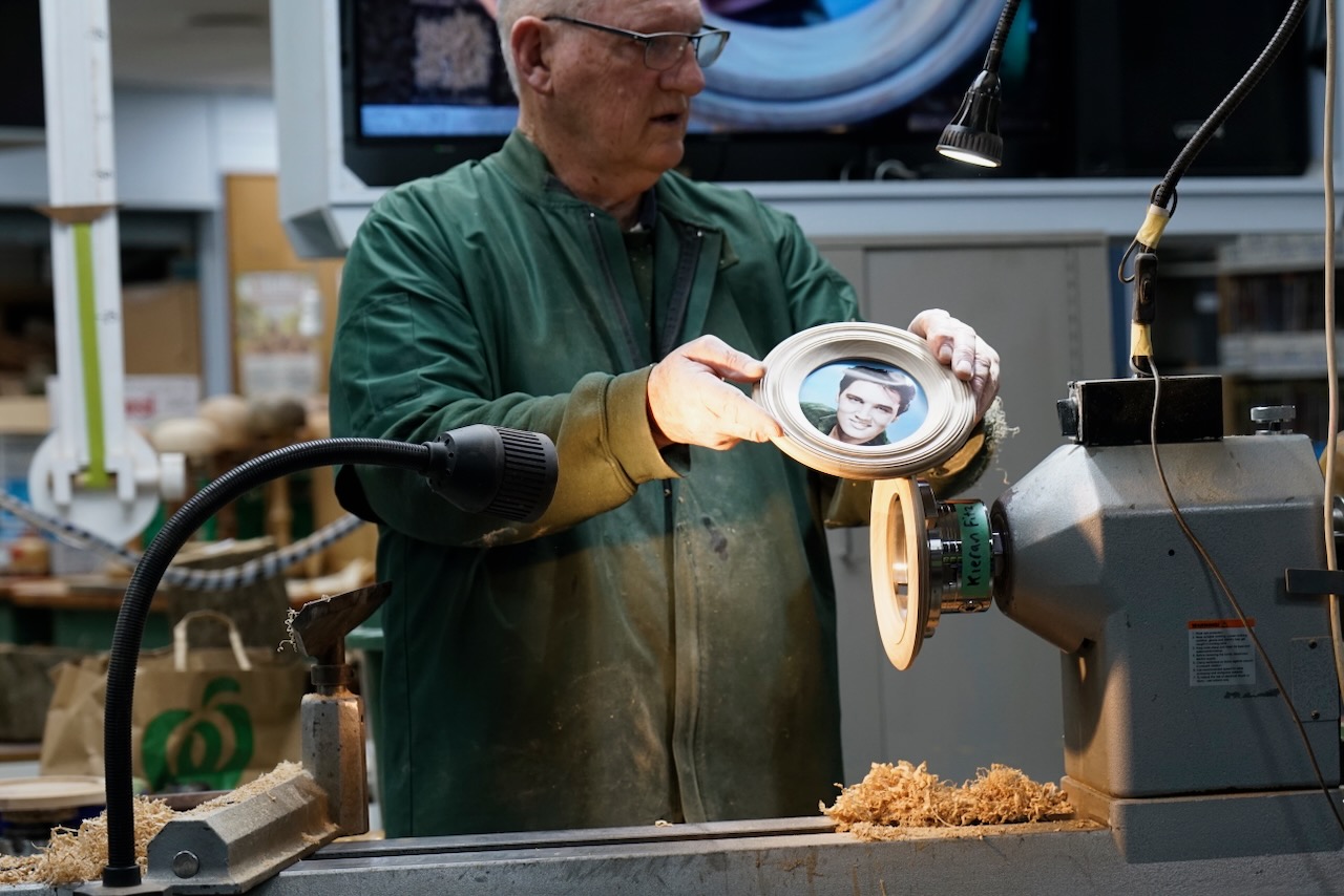
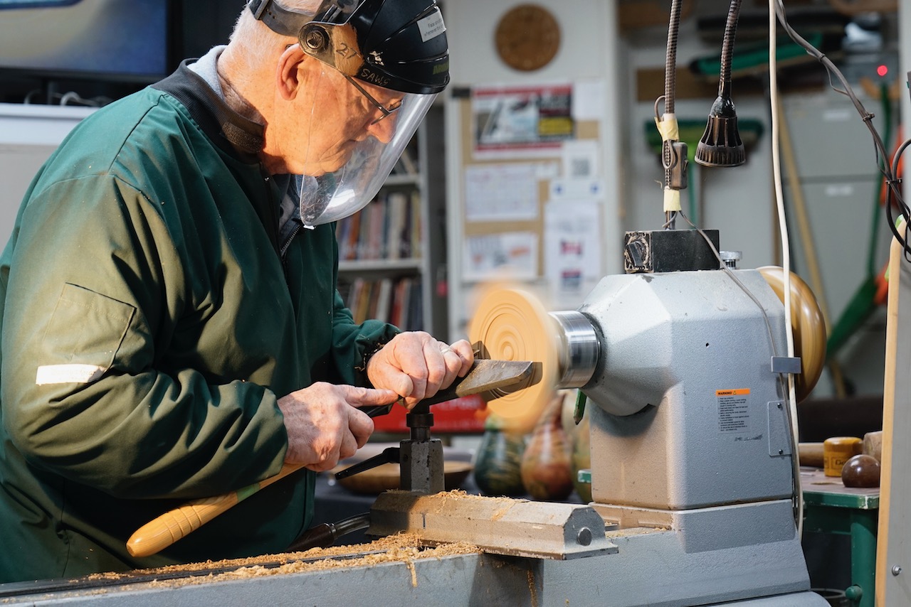
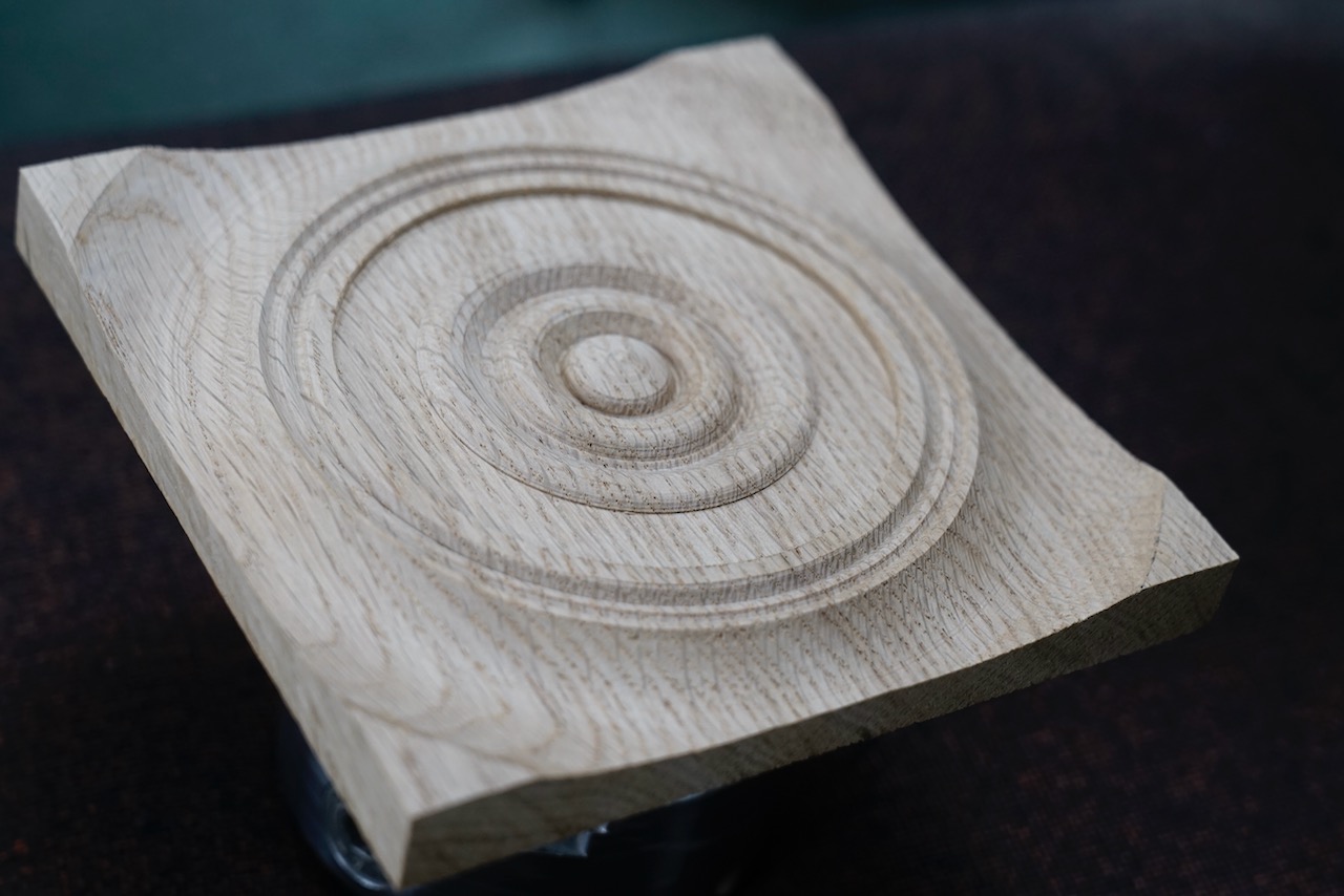
The plate has a lot of detail on the base, 4 feet on the corners and then the top can be embellished with pyrography, acrylic paints, pencils. A square or round border can be added to frame the art, or the art can extend outside part of the border.

The turning on the base varies depending on whether a tenon or recess is used. For a recess often use a 100mm chuck but 50mm also works.

All pieces have a lacquer finish.

Start at the table saw, cut squares from 20mm board approximately 170 x 170. Check for blemishes and decide top and bottom. Mark the centre on the bottom with an awl. Roughly sand the top to provide adhesion for the glue.

Mount a round glue block approximately 100mm diameter in a 50mm chuck. Face off the front of the glue block.

With the live centre in the previously marked centre hole on the base, bring up the tailstock to secure the board hard against the glue block.

With a hot glue gun hold the board in position with 5 large blobs of hot glue. For best results ensure the glue is very hot when applied and is allowed to cool thoroughly.

The tail stock is not required.

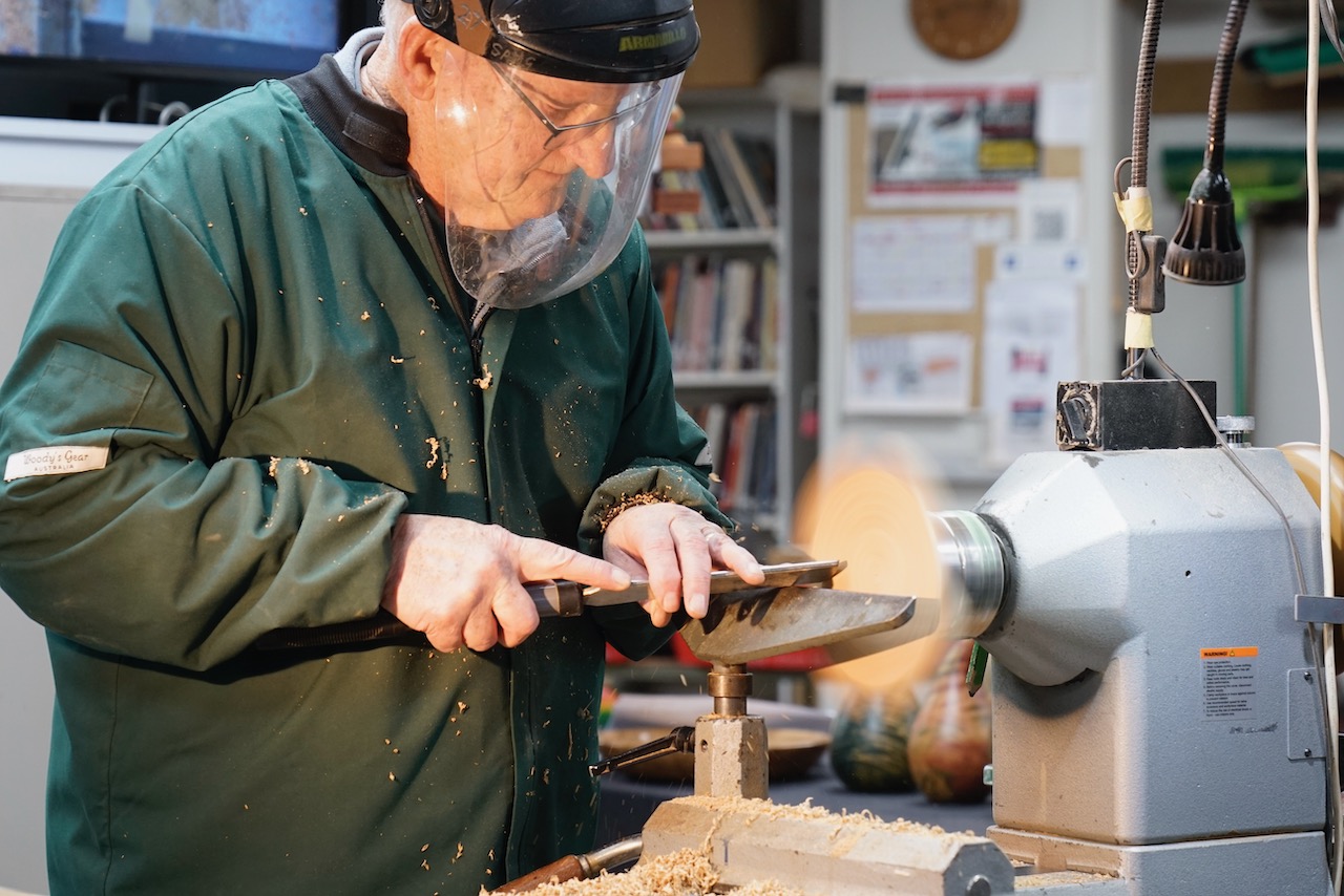
When the glue is dry, face off the bottom of the blank – use a draw cut to ensure the bottom is flat – particularly all 4 corners which will form the feet and must be flat. Tool rest is low, handle is low.

Now lift the tool rest to work on centre and make the base slightly concave so only the feet will sit on the table. Need to go from the very outside so need to eyeball the corner and push cut to the centre.

Use calipers to mark out for the recess – tool rest on centre, measure 97mm to fit 100mm chuck.

Mark the inside edge of the feet.

Grab a pencil and decide on the decorations for the base, mark the cut lines for domes and beads. If lines are to be erased later, use a soft lead like a 6B.

Drop the tool rest, cut the dovetail recess – initially with a parting tool – 2 to 2.5mm deep and approximately 10mm wide. Cut dovetail with homemade scraper tool – hold the handle slightly above horizontal to make the dovetail.

With a 35o bowl gouge, start at the centre shaping domes and beads across the centre of the plate. Width and position can be quite random.

Outside this embellishment need to cut away any excess timber to form the 4 feet which must be proud – check this before proceeding.

Now use a round nose scraper to refine the concave area working towards the outside of the base.

Sand this area (hand sand on lathe). Note that oak is quite coarse, so you do not need to be so fussy with grain.

Use a heat gun to soften the hot glue and remove the waste block from the plate.   Remove glue from the glue block so can reuse it.

Remount the piece on a 100mm chuck using the recess on the bottom.

Note: if using a recess this can weaken the piece so care when removing wood around it.

Check the front is flat – it is important that each corner is at the same height. Use a draw cut to make the front true if required.

Carefully start at the corner, cut a concave shape with a bowl gouge. If you leave the centre in this gives a visual guide as to how thick you are getting at the edges. Aim for 4mm thickness between the feet.

Remove the centre excess, clean up the surface with a scraper.

Sand – either with an electric drill and mandrel with lathe turning or it may be necessary to sand with the lathe stationary. Recommended to sand to 240 then a light touch with 320 grit before pyrography to make it easier to apply burn patterns.

If you want a round frame for the art, draw this in now with pencil using the lathe. For a square frame place plate flat and eyeball with a ruler and pencil.

Remove from the chuck and sand the edges.

The detail on the back is the first embellishment, the second is the drawing.

Choose your image. If it is a photo it can be helpful to divide the image into quadrants so when you draw on your plate you can retain perspective.

Mark the quadrants on the plate (within the frame) then draw the shape with soft lead pencil.

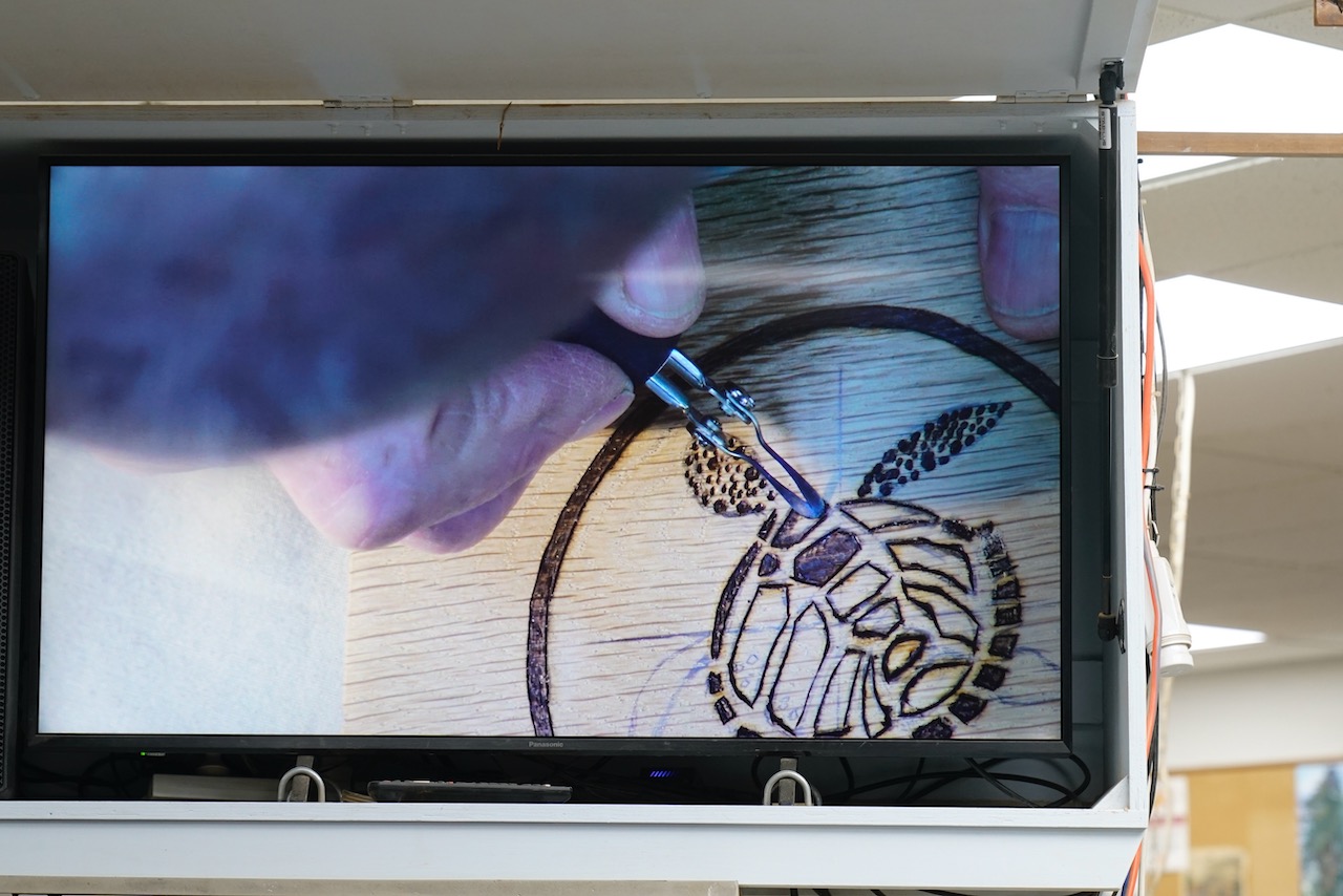
Using a pyrography pen, follow the pencil lines.

Kieran uses a Razertip burner which doesn’t burn as hot as the Burnmaster but is suitable for finer art. Can use a rice bag to stabilize the piece. For straight lines uses a medium size rounded skew or rounded knife point nib.

Pyrography lines do not need to be exact.

Draw the burner nib in towards your hand.

Hot tip is cutting in to the wood which helps stop the shading nib from going over the line in a later step.

Change to a writing or drawing nib and make a series of dots moving along the pencil line initially then fill in the centre.

Change to a spoon shader nib to fill in shapes – can use a swirling motion or dab the nib. To darken, just go over the area again.

Any overburn can either be sanded away or removed with nail polish remover.

Rub out any pencil markings and bush the rubbings away before colouring.

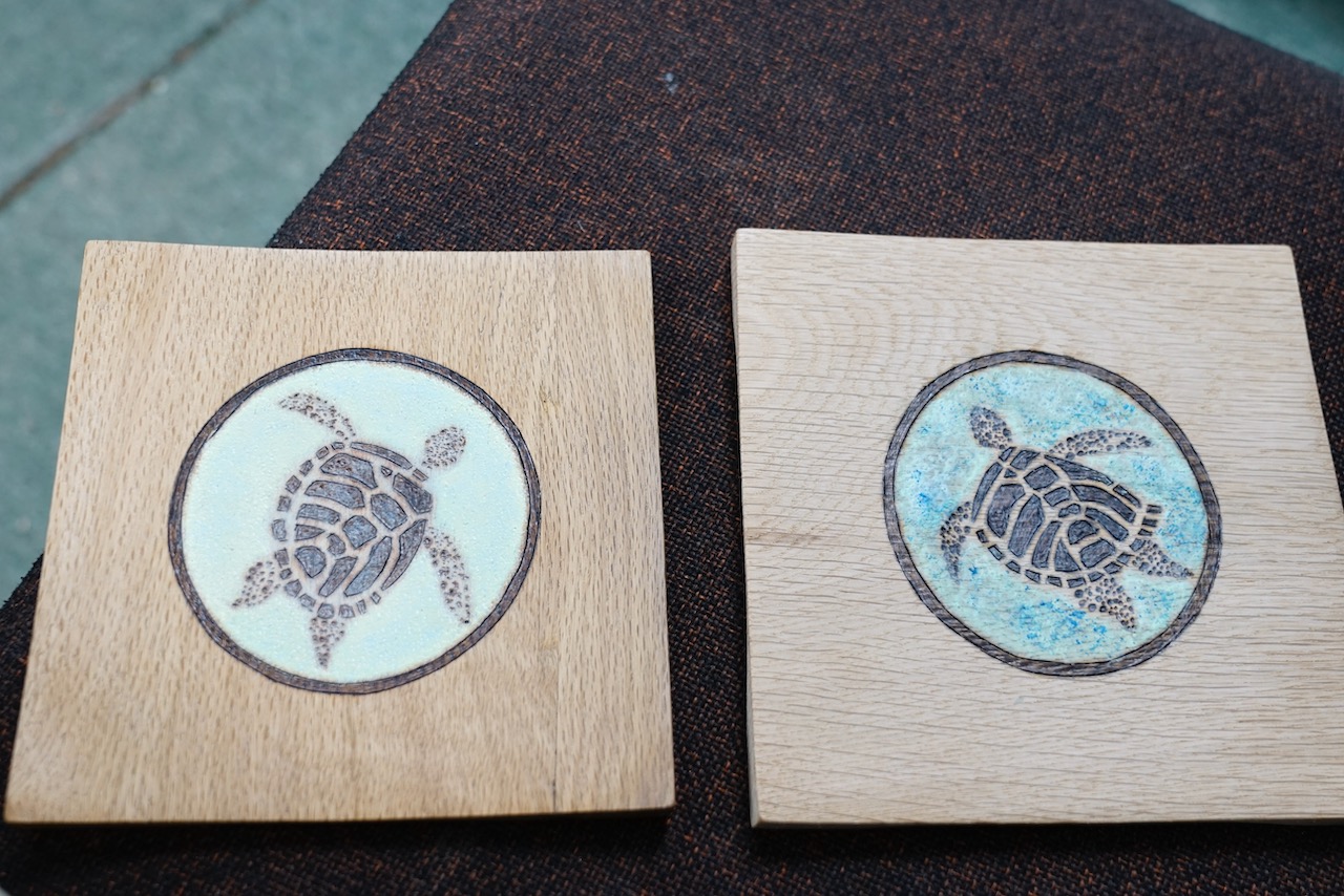
For the sea Kieran used 2 colours of acrylic paint (purchased from $2 shop) cream and teal. Blend the colours to get the shade you want, apply with a damp sponge – this gives a texture to the finish. If there is excess paint, over lines etc, remove with a damp cotton bud. Dry (to speed up process can use a heat gun). If the cover is splotchy, recoat when dry.

For the turtle body make a white wash with white paint and add water from a spray bottle to get very dilute paint. Using a clean sponge, dab it over the turtle to have an overall painted look while retaining the “character” of the turtle. Dry the white wash.

Now can dab on another colour over the water section – Kieran used deep blue mixed with white to subdue the intensity. Dab on with a damp sponge, spread the colour around to make it look like water.

Coat with 30% gloss lacquer.

Once piece is lacquered and dry you can go over the surface with 0000 steel wool but NOT on any coloured areas.

Jon Pearse – Making Woodturning Tools

Club Meeting:  17 June 2026
Report by:  Kieran FitzGerald

Tonight Jon captured our attention by:

  • demonstrating how to turn wood with a banana
  • exhibiting several beautifully crafted woodturning tools that he had made at home, including two scrapers, a skew, a parting tool, a knife and two captive ring tools.

However the tone of the evening changed as Jon morphed into mad scientist mode and delivered a full on lesson on metallurgy as it relates to various types of steel.  Let’s unbundle some of what he told us and try and make sense of it.

The underlying theme throughout the presentation was making woodturning tools at home.  But first there are some basics to understand.

What is steel?  Jon advised that while iron is the key component of tool steels, carbon the element is an important component which determines its hardness and therefore its suitability for tool making.

Type Of Steel:Iron (Fe)Wrought IronLow Carbon Steel e.g. 1018Medium Carbon Steel e.g. 1045High Carbon Steel e.g. 1095Cast Iron
% of Carbon:0%Up to 0.03%Up to 0.3% 1 HRC0.3 – 0.6% 10-55 HRC0.6 – 2.0% 11-66 HRC2 – 4%

Simply put, the more carbon the harder the steel can be made by heat treatment processes.  The Rockwell scale is used to measure the hardness of steel, expressed in terms of HRC. For example 1095 steel is purchased in an annealed (soft) state which is around 11 HRC. However it can be hardened up to 6 times that hardness with heat treatment processes. 1095 is a good candidate for making woodturning tools.

How do you know what type of steel you have?  Compared to identifying wood, it is very hard to identify unknown steel that you have found under the bench in the workshop.  A metal analyser costs between $30,000 – $60,000 and is out of reach for home users.  A magnet will stick to carbon steels, but it can also stick to some stainless steels. A spark test can be used to get an idea if a piece of steel has high or low carbon content. When putting steel to the grinding wheel, a low carbon steel produces longer, quite straight sparks, while a high carbon steel produces sparks that burst and fork like fireworks. That would indicate a higher carbon content, but it will not tell you the actual percentage of carbon in the steel. For that reason it is recommended to source your steel by name from a known steel company.

What is heat treating?  Whilst the amount of carbon determines how hard a piece of steel can be hardened, too much carbon (over 2%) would move it into the category of cast iron. Cast iron may be hard, but it is not tough. In fact it is quite brittle, and therefore unsuitable for making woodturning tools. 

When making tools you need to consider both hardness and toughness. The hardness of steel is altered through a heat treatment process called hardening. The steel is brought to a specific temperature where it becomes non-magnetic, and then cooled rapidly. This process makes the steel very hard, but it also becomes very brittle. Another heat treating process called tempering is required to take away some of the brittleness and to give the steel more toughness. 

Jon talked about four heat treating processes:

  • Normalising returns the steel’s grain structure to its normal state. For example, steel from a blacksmith’s forge is hammered into a particular shape. During that process the grain in the steel becomes ununiformed in size. To normalise the steel it is heated close to its hardening temperature and then air cooled.  This creates a uniform grain structure and relieves the internal stresses caused during fabrication.
  • Annealing is similar process to normalising but the steel is usually cooled very slowly in the forge once the heat is turned off.  Annealing makes the steel soft so that it can be easily worked, shaped and drilled if required.
  • Hardening involves heating the steel to a high temperature where it becomes non-magnetic. Then the steel is cooled rapidly by quenching in solution of water, brine or oil.  This locks the carbon into the iron’s grain structure making it very hard, but very brittle. The cooling solution depends on what type of steel you are hardening.  
  • Tempering is an important process which takes away some of the brittleness and gives the steel more toughness. With tempering, the steel is held at a set temperature (200C) for two hours and then air cooled.

Jon used an HRC hardness testing file set to do a scratch test on a sample piece 1045 steel rod.  He heated the tip of the rod with a gas torch until it was cherry red (at which point it became non-magnetic).  Before heat treating, the HRC40 file could cut into the rod, showing that the rod was lower than HRC40. But after the heat treatment process the rod tested between 55 and 60 HRC with the files.

Jon also demonstrated with de-galved fencing wire how the qualities of the wire were affected by different heat treatment processes. Wire samples were heat treated to show the normalising, hardening and tempering processes. Unfortunately the piece for the tempering process did not work well and while his assistant should have struggled to straighten out the wire, he broke the wire in half. The wire broke where there were no temper colours and therefore it was still brittle in that area. 

Steel responds to heat by changing its colour as it gets hotter.  Jon showed us a piece of flat steel plate which he had heated earlier and the temperature colours ranged from straw (around 200 degrees C) through to grey (above 350 degrees C).  Each colour change occurs at a definable temperature. During the tempering processes the temperature can be observed by the straw colour of the steel.

Having talked through the heat treatment process, it was appreciated that most of us do not have a forge.  Jon introduced us to a source of steel which is already hardened and readily available at home.  This is the humble file.  The home-made tools that Jon passed around at the beginning of his demo were all made from files.  He explained that not all files are suitable but it is easy to work out which ones are by gripping the file in the vise and trying to bend it.  It will either break cleanly or it will bend.  If it breaks you will be able to see if it has a fine grain structure or a coarse grain.  The file you should use should have a fine, even grain structure.  For the record, files are described by their types as follows:

  • The through hardened file – clean break with very fine grain, this is the file you want to use for the tool.
  • Fools through hardened file – clean break but coarse grain, no good.
  • Soft as butter file – bends easily (typically rasps), no good.
  • Case hardened file – bends easily. These are typically files that cut metal, but are no good given their soft as butter interior.

How do you shape your tools?  Use your angle grinder with a cut-off or skinny disc to make the basic shape. Use a grinding disc to tidy up the cuts and to add radius curves as required. Finish by using a flap disc or belt sander to remove mill scale and to make everything flat. If shaping a file it is very important to keep the file cool during these processes. Files are already hardened and any heat over the tempering temperature of around 200 degrees will soften the file and the tool will not hold an edge. 

Once you have made your tool from a file, it still needs to be tempered.  Jon’s suggestion is that this can be done in the home oven by heating at 200C for two hours and then allowing it to cool naturally in air on the bench.

Other suitable materials for tool making are HSS hacksaw blades and planer blades etc.

What is HSS?  HSS stands for high speed steel.  It is a high carbon steel with a range of additional elements such as tungsten, chromium, vanadium, cobalt, molybdenum etc.  It is very hard, retains a good cutting edge (although it cannot achieve the sharpness of carbon steel), and it is more forgiving when overheated compared to carbon steels.  

Jon’s presentation was successful in maintaining a very high level of audience interest throughout.  It was delivered with high doses of humour and audience involvement, used easy to understand terminology and was well structured.  Thanks a heap Jon.

Pete’s got wood, and much much more.

Club Meeting: 6 May 2026
Report by: Cory Wyatt

Pete and Michelle

To say Pete’s got wood, is like saying the ocean is wet. True, but it is an understatement of all understatements. Pete has done most things with wood, and has several firewood yards to go with full sheds at home. The quote of the night was “you gotta have a wood cutter, to have a wood turner”.

 Pete told many stories, funny and in some places illegal stories that explain the man and couple. He has borrowed wood, cut wood with everything you can think off and builds benches, table tops, to works of Art. Developing from Wood cutting to wood working with turning a part of the journey he has spent many hours in the shed like most of us. He is also a proud home kill butcher and a proud member of the Geyserland Guild of Woodworkers (https://www.ggw.nz/) in Rotorua.

His partner has helped him on the way and allowed him to store many of his works in the house including some of his 650 axes’. He may have the best and biggest axe collection in NZ, including many rare early NZ made.

While the stories were very entertaining what stood out was Pete’s willingness to share his knowledge. This included many learnings around what to take in your chainsaw kit.

  1. A Chainsaw Bar vice, which can be found for as cheap as $20, used to help with sharpening.
  2. Chainsaw spanner, wedges, blocks etc
  3. Sharpening Guide and tools
  4. Oil, a mixture of used compression oil/vegetable oil, with a ratio of 30 to 1

If you are ever in the Rotorua area or in the greater Bay of Plenty and in the need of firewood, give him a call.  

Jonathan Heather – Lidded Box inlays

Club demo: 28 May 2025
Report by: Kevin McFall

Jonathans demo of doing inlays into the lids of lidded boxes was creative and practical.

The Box

Jonathan started with a 90×90 block of Macrocarpa. This had the centre of each end marked and was placed between centres on the lathe and rounded off.

The rounded blank was then marked up where the tenons for the lid and base would be and where it would be paired off to separate the lid and base (Note the lid needs to be extra thick so was made about 12mm).  A parting tool was then used to make the spigots at both ends and the lid and base of the box were then separated using the parting tool where he had previously marked it.
Jonathan then brought out a pre-turned box base, mounted the lid in a chuck and turned this to have a tight fit on the box, but ensuring the lid was about 10mm thick at this stage.

The Box was mounted in the chuck and the lid fitted on and taped into place for added security.  He then turned off the tenon from the top of the lid and cut the rebate for the inlay.  This rebate left a 5mm rim and was about 5mm deep.

The Inlay

The inlay was glued to another piece of wood that was to be a spigot for the inlay.  This had been pre-turned to size.  Once the glue had set the inlay was placed into the chuck.

The inlay was then turned to size checking regularly with the rebate in the lid.  You need to make sure the chisel is very sharp so that if the inlay wood is ply or spalted, it will not tear out.  Taper the inlay slightly to get a tight fit.
The inlay was then glued into place using Tightbond (or another similar glue can be used).  Once set the lid was put back onto the box and taped for safety and the waste wood (the spigot for turning the inlay) was turned off.

The inlay was trimmed up to flat, in this case as Jonathan was using spalted wood superglue was dripped into it first to stabilise the wood, but sanding sealer can also be used.
Jonathan also showed a few other inlay lids he has completed.  Some of these were done with soft grain woods (such as Norfolk Pine) where some of the grain is burned away first and brushed or sanded out the burnt soft wood.  These can then be coloured or finished with wax or oils depending on the look desired.

Jonathan did an awesome demo and really showed great ways to make a box look special and have some additional artistic flare.

Dave Anderson – Balusters

Club Meeting: 3rd June 2026
Report by Bob Yandell

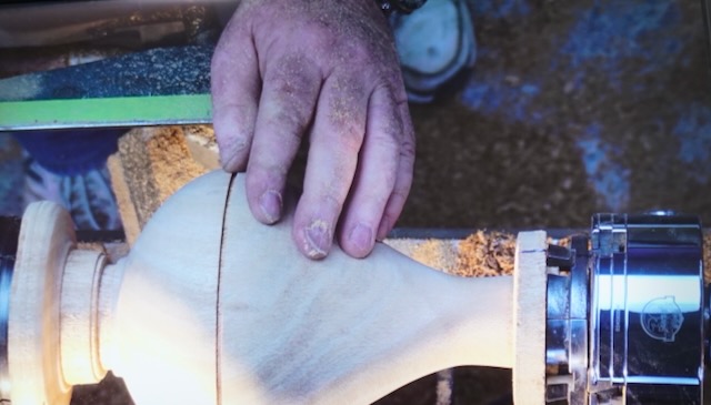
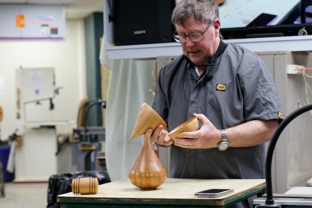
Dave Anderson, Life Member of West Auckland Woodturners Guild, demonstrated how to make a Baluster. It was Dave’s third demonstration on this subject to our Club and 18 years since his last which saw members, both past and present, make the Balusters that adorn the wall and sides of our demonstration seating area.

Dave served an 8,000-hour apprenticeship followed by 19 years working in the furniture industry before seeing the relaxation of import restrictions on the importation of furniture and the demise of domestic production. Dave now spends his time producing replacement Balusters for the restoration of older villas and buildings plus bespoke balusters for new builds. Regulations have seen changes to heights of stairway rails and gaps between balusters so if we are thinking of doing any check the regulations – replacement is different from whole new staircases.

The profile of a Baluster is either symmetrical or asymmetrical. The asymmetrical bottom half tis a mirror image of the top. The squared end at the top is shorter than the bottom.

The wood used in demonstrating the process was H3 pine dressed 4 sides and 75mm square. Dave uses supplied timber at 75, 65 or 58mm square and 950mm in length for standard balusters. Bespoke dimensions are determined according to need.

The wood is mounted between centers and alignment defined by visual and adjusted by tapping with a hammer. The top end of the baluster is at the Headstock end. Mark the length of the top end by putting a notch/cut with the skew.

Using the Roughing Gouge round the between section. Mark the profile change points. Working along the rounded shaft mark all the high points.  Shape using a combination of Roughing Gouge, Spindle Gouge. Leave the low points last to ensure strength. To assist making a smooth cut. Dave used the thumb of the hand nearest to the cutting edge to hold the tool onto the wood. The design is a combination of fillets, coves, beads and tear shaped curves.

Tip from Dave –

To determine the balance and esthetics of items such as table legs to make and stand it up: step back and view from a height and distance appropriate for the finished product. Adjust profile to achieve balance then proceed to produce the remaining 2/3.

View Balusters and Finials on the old Villas in the older suburbs to get an appreciation of what works,

Dave used a spigot gauge to ensure that the spigot was constant in diameter (an open-ended spanner will also do), Chamfer the end and cutting a groove in the spigot will allow trapped air in the drilled hole escape when the baluster is inserted.

Project – 

Members are challenged to make a Baluster to be added to the existing. The specifications are:

Finished length 500mm; squared ends 75 x 75mm; 20mm spigots at each end.