Category Archives: Reports

Offset Candle Holder – Richard Johnstone

Club Meeting: 23 September 2015
Report by Colin Wise

A set of plans is available here

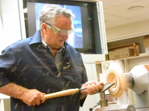
Richard set the piece of wood in the lathe between steb centres, setting speed to around 2000 rpm. Turn to a rough round with a roughing gouge then explained that Warwick did it this way, Dick action went something like this, Phred will use a skew like this, while Terry winds up the speed and with the roughing gouge fires chips everywhere, Terry to a T.

IMG_9058

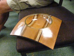
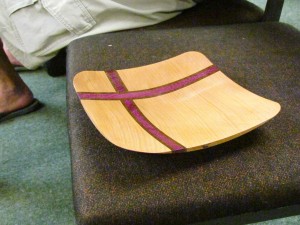
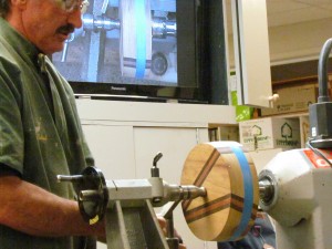
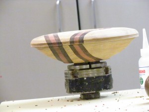
Richard went on to make quite a respectable shape with the 2 centre piece. Then went on to one he had started at home, which has 3 centres, giving a twist effect. Showing 1 to 2, 2 to 3 and 3 to 1 then said it was easier to colour the centers, red, green and black and do it red to red, black to black…

IMG_9067

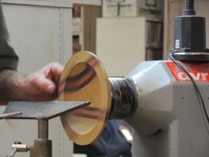
He turned it using a roughing gouge and the the skew, with a slight whoopsy. Finishing it off with a bowl gouge, making it a very interesting evening.

IMG_9068

Well done Richard.

Off the Edge – Gary McDonald

Club Meeting: 16 September 2015
Report by : Alan Day

Gary shows us half a dozen trial pieces of work he had to do to get it right !  The inspiration of this piece came from Barbara Dill.

While starting his project at home, he had a loose fitting garment, and unconsciously slid it over the tool rest, while he was concentrating on the job in hand of trying not to let the off centre work strike him in any way ! now his left arm is entangled with the tool rest, he was trying to turn the lathe off, but couldn’t reach it with his right hand ! but eventually managed it ! phew, now he has a remote off switch, – once bitten !

IMG_9830

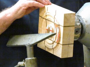
For our Demo he has a block of timber 110 x 110 x 130 mm, makes lines both ends from corner to corner, makes a centre mark, then another centre mark 35 mm along one of the lines, and at the other end a similar mark but in the on the other side of the centre mark, so it will look like a diamond when it is spinning !
Using a hand drill with a Forstner bit in, he drills shallow holes at a slight angle so when he has the block off centre, the two steb centres, one as a driver, and the other live,  will have a flat surface to push into. Gary offers the block up to the headstock steb centre, he brings the tailstock up and locks it with the Handle on the downward side, as recommended by Champion Wheel Maker – Brydon,

IMG_9837
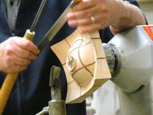
The work is marked around with black lines to help guide the gouge while it’s spinning, and blue lines to show where the sphere will be, a 100 mm tool rest is brought up,and the block spun by hand to make sure it is all clear, Gary has a long Carbatec Universal Gouge handle, and fits a Bowl/Spindle Gouge with a 30 deg grind to it, gently offering it up to the spinning block rotating at 500 rpm, and we can hear the hit and miss, tic tic tic as the wood spins, and Gary is watching not the gouge, but the shadow on the top, working one side, then the other gradually deepens a groove, while pressing down the gouge firmly on the tool rest, to get a clean cut.

Gary stops the lathe to measure the width of the gap, and now he can change the 100 mm rest for a 30 mm to fit inside the groove, scary turning eh !
Gary recommends reading the article on Off Centre Turning by Barbara in the AAW magazine, now making deeper cuts while the wood wizzes past at an alarming rate, not a time to lose your concentration !   Now turning a ball at the bottom of the tapered groove, and widening the sides, Gary says be careful not to hit the right side while widening the left  or vice versa, now cutting the base next to the headstock end, he says Nick Agar uses an under hand grip, not possible with this rest,

IMG_9841

He has made a `Bow Sander’ to sand the ball, so instead of a bowstring, a long strip of sandpaper is stung between the ends, so he is able to sand the little ball while keeping his digits away from the spinning work, he stops the lathe and uses a Hot Melt Glue Gun to glue wedges in to support the unsupported nascent sphere, he says Barbara turns at a higher speed, and gets a better finish off the gouge,  check out the Web Site on Multi Axis Turning, doing lights cuts outside the tailstock end, and quickly gets the required shape. He recommends a book by David Ellsworth which suggests keeping the right hand further back on the gouge handle for greater control/leverage, left for left handers, he says one time he was at home and had to re-tighten the tailstock out several times, only to find the headstock was moving backwards !!
IMG_9851

Speeds of 800 rpm now, holding his gouge handle close to/touching his body, he didn’t complete the Off The Edge Sphere, but says at home it takes about 1 & 3/4 hours.

Questions are asked for, and answered, this was a really good demo, – of something we might not have thought of trying at home,
Thanks Gary for showing us how to, and not be afraid of the spinning lump of timber !
Cheers Mate,
Alan Day

Dust Protection and Extraction – Warwick Day, John Whitmore

Club Meeting: 9th September 2015
Report by: Kevin Reeve

A synopsis of the general theme of the two main topics covered by the presenters, Warwick Day focused on dust protection for the “turner” whilst John Whitmore would later follow on illustrating how to eliminate dust totally from the environment by wet sanding.

The presentation was started off by Warwick, who identified specific areas to minimise dust, affecting the person.

Design
Dust potential starts well before you even turn the lathe on, so deciding what you are turning has an impact of the volume of dust created.  As an example, thought should be given to whether you are turning end grain, which creates a lot more dust, or cross grain, which in general has less dust.

Wood Type
With any wood turned, shavings and dust are the resultant effect.
Those that are more sensitive to dust should consider using a harder wood to turn, such as walnut or Black Marie.
Some of the softer woods do create more dust, so this needs to be another consideration for minimising the effect of dust on the person, and your work area.
An example, demolition rimu, where the fibres in the wood exhibited some rotting, created a lot more dust.
In general, the lighter the wood, the more dust there will be Warwick says.
A question was asked from the floor about spalting, and the risks.
Spalting is any discolouration of wood caused by fungi.  Research has identified that it can be found in a living tree, a tree under stress or a dead tree.
The area for concern for the turner are the fungi pores can have a detrimental effect on the lungs, as well as your skin. Coupled with this there needs to be a consideration about the types of wood you are using which may escalate the risks.
This lead to a discussion about toxic wood.
The beginner guide does cover toxic woods, and will not be expanded on this in article, as it is a very specific field, and a topic which can be covered on its’ own merits.

Tools
How sharp are your tools?
The question was put to the audience to get turners thinking about the tool they are using, and their condition.
The turner should not become lax in their tool maintenance, and at every opportunity where there is some trepidation about the quality of their tool sharpness, it should be remedied.
The sharper the tool, the less dust.

Levels of Dust Protection
Masks
There are a variety of dusk masks of the market, both in quality and specific use. Careful consideration must be given to both how they fit the user, and the level of dust protection they provide.
Dust masks have various ratings for example P1 P2 and P3. If the reader requires an in-depth description of the mask ratings, they can go to:
http://www.business.govt.nz/worksafe
There is a good amount of information on this site to assist the turner.

IMG_8976
Full face dust protection
Warwick demonstrated the AC400 full face enclosed dust and face mask system. The advantage of this system is the battery is enclosed in the head unit and can provide up to 8 hours plus service.
The unit describes as providing full air filtration.
The face shield is rated at 90 kilo Newton’s.  As a comparison, the clubs shields are rated at 70 KN

Vacuums cleaners, Air hose blowers, and Fans
Warwick completed the first part of his presentation of 3 other devices. His number one tool in the shed was a vacuum cleaner to clear and reduce dust.
Secondly, he pointed out the disadvantage of using an air hose to blow dust everywhere, the more dust you blow around the more dust you are working in.
Warwick touched on the use of free standing fans, and the benefits and blowing dust away from the area you working in.
These can be beneficial combined with a good extraction system, and perhaps fresh air.
This lead on to a discussion from the floor that dust in the workshop can present an inherent risk of being highly combustible if not attended to.

Hand and power sanding tools
Warwick exhibited the different types of power sand tools.
His preference is the inertia type sander with the lathe running at a low speed.
The advantage he suggested was there was less heat created through rotation from two seperate electrical power sources.

The next part of the presentation was from John Whitmore

IMG_8992

John’s suggested there should be no dust at all.
Speaking from experience, John turns inside his own home, and albeit a few wood shavings in the house, he has attempted to eliminate all dust in the environment.
John commences his presentation by offering free dusk masks to everyone.
John introduced his presentation by saying humans have lived with dust for “millennia” and because of our ability to get rid of dust through lungs and their biological efficiency.
He went on to say that because of the industrial revolution, our natural ability to do this has been nullified due to exposure to external chemical variants that we would not have been exposed to.
There was some brief discussion around asbestosis, its’ origin’s and use.
He presented a wet sanding solution using 100 grit sand paper and Ondina oil which is produced by shell petroleum. (Research can be done by looking up the product)
There was discussion about the limitations with finishing whilst using this product.
The merits using this way of sanding were presented were twofold:
Eliminating dust by creating a slurry effect on the Astra paper
It cools the wood
A comment from the floor suggested any type of small brush will remove the slurry and one can perhaps use WD40.

IMG_9003
The next part of the presentation was again from Warwick about machinery and dust extraction using various machines from manufacturers, but due to the extended time taken with the meeting it is an area that should be looked at again.
A big thanks to Warwick and John. An extremely informative presentation about dust and how it can affect turners, and something we should all consider.

Making a Mallet – Phread Thurston

Club Meeting; 25 August 2015
Report by David Jones

Phread  started his  demonstration by making a mallet in under 2 minutes without using the lathe at all.- simply cutting a piece off 100X75mm radiata post, drilling a hole through it with a forstner bit, cutting a length of dowel for the handle, shoving it into the head and walking away.
IMG_9764
Clearly a very impressive performance from a speed point of view, but a rather useless mallet , unlikely to last..

IMG_9766

Phread then proceeded to give an excellent demonstration on basic woodturning, and the importance of accuracy depending on the requirements of the project.

He started by showing a spurtle and a doris, both particularly shaped pieces of wood designed to stir food in a pot, and both made with a spoke shave . They were both beautiful to look  at as well as excellent in doing the job they were designed for, demonstrating the use of the spokeshave and the effects of cutting with and against the grain.

The head of the mallet had already been drilled for the shaft, but as the head was to be turned off-center, Phread then spent some time discussing the need for maximum accuracy in marking the exact center of each end of the mallet head and the use of the right sized ruler and the making of the point with an awl rather than a builders pencil. The ends were marked with diagonal lines as well as right angle lines through the centre of each end and four offset points 10mm each side of the center.

IMG_9772
The head was then partially turned between centers before being offset 4 times using the 10mm offset points previously marked. The head was then sanded along the grain.
Putting the mallet head back on the lathe between centers, Phread then demonstrated marking and cutting the mallet head to the exact length required using a parting tool and then a skew chisel to cut off the torn grain and remove the arras  on the edge.
IMG_9777

The handle had a sawcut put in it about 50mm long to take a wedge and was then roughed about 32mm except at the end where the wedge cut was where a taper was put on. A very wide cove was then put into the handle with a large spindle gouge, before Phread reverted to his favorite skew chisel to finish the bottom end of the handle and the taper so the handle would fit through the hole in the head of the mallet. All this time he was demonstrating how to stand and hold the tools so that there was minimum effort. He also pointed out the need for the wedge direction to be at right angles to the mallet head direction, to avoid the mallet head cracking when fitting.
IMG_9789

Thanks Phread for an excellent demonstration about the real basics of woodturning which are so essential for our craft.

The Last Drop – Dick Veitch

Club Meeting: 19-Aug-2015
Report by:

By my count eight axes less than the “Bean” this time a modest five, this multi axis demonstration is an adaptation based on a Mark Sfirri turning. The intention is to portray squeezing the last drop from the bottle.

Dick started with a piece of Taraire (Beilschmiedia tarairi)100mm square by 270mm long.  The SAWG Beginners Guide to Woodturning states about Taraire “May be described as a slightly pinkish tawa and some heart wood can be brown. Turns easily and polishes well.”

Now from here on this report is a rather easy affair and you have two options you can skip to the Projects page and down load the PDF titled “The Last Drop” here Dick has again provided yet another  excellent resource sheet, or plough your way through my ramblings.

At one end mark centre on the other end markout and then label the five axes A through to E all these are marked on one diagonal, for a very accurate layout a knife instead of a pencil may be utilised with the use of an awl to mark the locations.
IMG_8817
Mounting the blank in a 100mm chuck down to round for roughly half of the blank to approximately 65mm being the size of the base of the selected bottle then part off 100mm up from the base with a double cut to form the base of the box.

With the remaining piece still in the chuck form the lid of the box, check squareness of the inner rim of the lid of the box with a straight edge against the bed of the lathe to ensure a good fit.

Mount the base in a chuck with some form of protection Dick used a piece of drain pipe, hollow out the inside, if using a forstner bit check there is enough remaining wall space verses the forstner bit selected size. With a freshly sharpened bit keep the bit moving when drilling and ensure shavings are exiting, turn the handwheel reasonably quickly.

IMG_8827

After hollowing out, tidy the inside base of the box with a Soren Berger or tool of choice. Next fit the lid to the box.
The following is the order for mounting B,A,C,D and E.

From this point on it may be easiest to refer to the project sheet, moving the piece between the various axes forming beads and coves on the neck with sharp crisp connections, along with the cap the bottle started to take shape. During these stages one could be forgiven if the connections between the various axes left them a little contemplative but by the time the final cut was made on axis E everything fell into place and the last drop emerged.

IMG_8831

Another well executed, informative, fun demo – thanks Dick.

Project Sheet :The Last Drop

Three Sided Bowl – Andrew Bright

Club Meeting: 12 August 2015
Report by: Phread Thurston

When Andrew showed us what he was about to demonstrate I thought “how the hell will he turn that and I hope it’s competed before midnight “.  Read this article and you will get both questions answered.

IMG_8766

You start with a piece of wood that is cut into an equilateral triangle say 45mm thick.  Mark the centre and mount on a screw chuck.  Face this off.  Remember the tip of keeping the tool rest parallel with the end result of the trued up face.  Sand when true, take off and repeat on the other face.  Both faces are parallel with each other and sanded.

Take it off the lathe chuck and all.  Now the next chuck that it was mounted on is not able to be described in this article.  It was an off centre adjustable chuck made by Andrew ( he has another life I think as a Fitter & Turner. ).  There are other ways of holding the work which is off centre and adjustable but this article is not the place to try to describe them.

IMG_8748

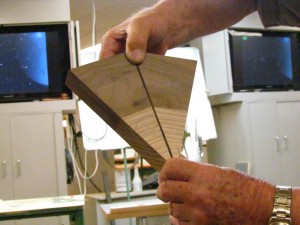
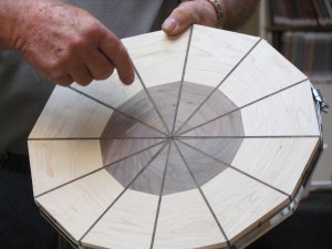
Before it’s mounted the circles require setting out.  With an equilateral triangle take a line from an apex to the centre of it’s opposite long side and draw a line.  Do this for the three legs of the triangle.  Now with a little trial and error work out a diameter for the circles and Andrew’s was approx 120mm.  Since the block is 45mm thick you can drill a hole in the centre of the circles to say 30mm and this will become the guide for the bottom of the bowls.  The bowls are then turned conventionally taking care that after the first, you will turn air and a little care is needed not to chip the bowl edge.  By using the adjustable off centre chuck the three bowls are completed and sanded up making sure you keep the three circles or bowl circumferences the same diameter.  Andrew uses sanding sealer after completing this stage.

IMG_8750

The back of the three sided bowl can be marked with the same markings as already described above.  Go to the band saw and cut from apex to the marked centre on the three legs.  There are many ways to sand up the three pieces but the sanding disc on the lathe with a supporting table on the lathe bed which was demonstrated worked real well.  Sand each piece, round the corners and do the top and bottoms.  In other words finish all the sanding at this point.
Using same contrasting colour wood and 10mm thick which has been dressed both sides mark out the three legs.  The style of leg and it’s position within the three sided bowl has more than one possibility and depends on how you want the end result to look.  A tip is to connect the three legs together and sand them connected so the end result is three equal looking legs.

IMG_8756

Everything all sanded and coated with sanding sealer it’s join up time.  This is really about patience, putting the brain in gear and it will go together.  Why don’t you try to make one.  I now know how and yes the demonstration was well done and inside the time available.  Thank you Andrew.

Triple Neck Vase – Colin Wise

Club Meeting Demo: 5 August 2015
Report by: Roger Wilson

Does three go into one….yes as demonstrated by Colin Wise

In the interests of a constrained time frame Colin elected to use less than suitable timber (too soft) in order to demonstrate the stage by stage process involved in turning this rather delicately trumpet fluted three neck vase.

Colin explained that in essence, you create three separate vases however a bonus would be in remembering ones school days geometry.
IMG_9694
It is critical at the starting point that the joining angle of 120 degrees is established and that the correct offset is marked..e.g. 16 degrees on the bottom (tailstock), 42 degrees at the top (headstock) which equates to a 15 degree offset over the 130 mm length.
IMG_9707
What was also demonstrated by Collin was his use of an ingenious wooden chuck shaped to hold the vase for both turning and shaping the trumpet plus hollowing out the vase. This chuck (attached to a set of cole jaws) piece of apparatus was the culmination of about two days work but once made would allow for multiple replication.
IMG_9713
Collin made use of his sphere turning setup to show how the perfect sphere can be produced in spite of working with soft  timber.

This stage by stage demonstration by Collin Wise showed that with patience what appears to be magic could, with care, be a reality for wood turners with some experience.
IMG_9720
A full diagrammatic description can be found on www.woodworkersinstitute.com (ed: not sure where)

Multi-Center Bowl – Dave Dernie

Club Meeting :  27 July 2015
Report by: Dave Armstrong

David started his demonstration by discussing the “Methodology” or the process of turning his pieces and showed us examples or his two types.  One being an oblong piece with three dishes and the more traditional round piece, also with three dishes.  David mentioned that it is possible to make pieces with more dishes (bowls) depending on the swing of the lathe and your layout.  Dishes could also overlap.  He showed us the process of designing and making suitable jigs and faceplates with additional sacrificial fixing plates.
David stressed the safety and balancing required, and the need for accuracy when marking out. Other considerations are aesthetics and the use of contrasting timbers along with the relation between lathe speed, diameter and chisel speed.
Throughout his preamble and demonstration he supported his comments with a very well-constructed PowerPoint presentation.

Demo – Oblong Piece

IMG_8677
David positioned his oblong stock on the oblong jig attached to the large faceplate which was swung at 45deg over the bed and turned the first outer dish.  He then made a template of the depth required to use as his guide for turning the other dishes.  Next he tipped his piece end for end and turned the second outer dish. Having completed these he then goes on to turn the centre dish and finished to suit.
He stressed the safety aspects concerning projecting wood spinning on the faceplate, keeping elbow into the body and also the need to ensure you mark out accurately or the dishes may not be positioned correctly.

IMG_8720

Round Piece

IMG_8676
David mounted his round work-piece to the large faceplate and proceeded to show the marking out using indexing and his drilling jig which was fitted to the banjo.  This ensures the dishes will be uniformly positioned around the blank. Each position was numbered.
The piece was then positioned at number one marking.  The complete faceplate and workpiece are checked for balance and the first dish turned and sanded.  Then he repositioned the work-piece to the next positions, balancing and turning until finished and sanded.

IMG_8706

As usual, considerable time is spent making jigs, sacrificial faceplates, and marking out etc. but the reward is a repeatable piece in the end.
Davids demo was so informative that everyone remained absorbed throughout and he fielded many questions at the end. Thanks David for your great demo.

Off-Centre Burl – Terry Scott

Demonstration Date: 23 July 2015
Demonstrator: Terry Scott
Author of Article: Wim Nijmeijer

Terry started by first giving us some general information about the wood, being Coolabah Burl (Eucalyptus Coolabah, found throughout Australia)
The burl is water blasted under high pressure to remove the bark and further processed in order to satisfy NZ customs. Typically there is a 24% moisture loss due to processing prior to importation into NZ.
Next Terry showed us a typical “flywheel” (can be made from custom wood or preferably from plywood)
The flywheel is used to attach the burl and also to balance the off centered burl.
A few examples of off centered turnings were shown.
Next the center of the burl was determined.

IMG_8646
Terry then demonstrated how to attach the wood onto the flywheel. This was achieved by using a packer board, spacers/wedges and a glue gun and plenty of glue!
The packer board is then positioned and fastened with screws to the flywheel. Terry then removed all this and replaced it with a pre-mounted burl already fitted to a flywheel. (Center of burl at center of rotation, tailstock in place)

IMG_8663
It was noted that this assembly was already sufficiently balanced.
The assembly was first rotated by hand before switching on the lathe at a slow speed, and then gradually increasing the speed to approximately 650 RPM.
The face of the burl was now turned. (Light cuts and rubbing the bevel)
Terry then showed us various pieces of lead used for balancing. Balancing is achieved on the lathe by attaching sufficient lead weights on the flywheel to offset the out of balance of the off centered burl. In this instance only 1 screw was used to balance the assembly.
With the tailstock removed the face of the burl was now completed using light cuts, followed by scraping.

IMG_8641
With the flywheel still on the lathe, the burl was removed. (Including packer board, spacers/wedges)
Next a number of overlapping off centered circles were drawn on the finished face of the burl.
Then the burl was fastened again to the flywheel, with the first bowl centered on the tailstock. The burl was then balanced as required using 3 lead weights secured with 2 screws per weight to the flywheel. Webbing can also be used to provide additional security.
The assembly was first rotated by hand again before switching on the lathe at a slow speed. (Beware of the off centered rotating burl)
With the tailstock removed the first off centered bowl was turned using a 35-degree bowl gouge. Terry then finished the bowl using a ring tool (tungsten carbide ring) starting at the bottom of the bowl at approx. 80% and then rotated slightly as the cut progressed to finish the inside of the bowl. The bowl was then finally finished with the use of a negative rake scraper.

IMG_8670
Next the burl and packer board were repositioned on the flywheel, by lining up the second bowl centered on the tailstock, and again fastened to the flywheel. This was then followed again by balancing.
The second bowl was then turned. First a 35-degree bowl gouge was used (light cuts, as cutting into the first bowl) followed by a 55-degree bowl gouge to finish the bottom of the bowl. Final finishing was done with the negative rake scraper. (Very light cuts)
The third off centered bowl, sanding and finishing with Danish Oil were not carried out due to lack of time.
All in all a very interesting demo with lots of additional information provided and as usual very well executed.
Thank you Terry.

Top Hat Egg Cups – Graeme Mackay

Club Evening;     24th June 2015
Report by:  John Smart

Graeme showed some of his work on these Egg Cups with hats on.
IMG_9641
He started with some of his thoughts & work on this subject as there are many options; Pointed versions ex Richard Raffan, Round & full bodied ex Grey Lynn.  Stories regarding Runny Eggs with lips to hold the juices.  Ice Cream look-a-likes all made from different timbers. He makes all of his from all forms of wood like Tasmanian Blackwood which after use ends up with a good gloss plus all other types of supplies coming from the firewood bin and ever looked at wood locker.

His next subject was PENCILS 3 years ago he purchased 3 dozen Pink carpenters pencils and since then has never found one where he stores them he of course blames the Nombessssss.

IMG_9650

We then got to the nitty gritty what size egg do we use and that required more discussion.  It ended up as a size 7 egg you will find all the dimensions in our projects file EGG CUP.

IMG_9663

Graeme created a entertaining evening and showed the skills he has plus a lot of technical advise that he uses which we can all adapt where necessary ourselves

IMG_9665
Projects File; Egg Cup

Thanks Graeme

John Smart