Category Archives: Meetings

Bowl Saving – Dick Veitch

Club Meeting: 4-May-2016
Report by:Gary McDonald

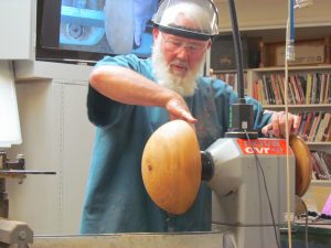
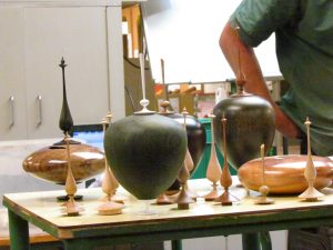
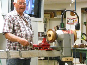
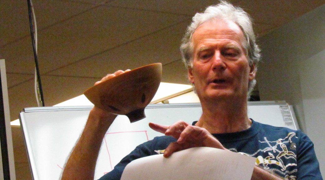
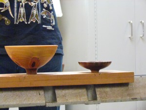
On display on table this evening were a set of four natural-edge bowl saved bowls from a pepper tree that Dick had turned some time ago – this term’s theme is Back to Basics, tonight’s topic was Bowl Saving.

Whilst commonly referred to as bowl saving, other terms may also be implied such as coring or centre-saving.
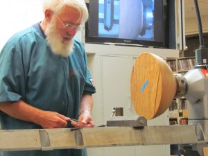
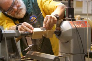
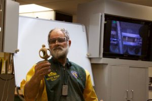
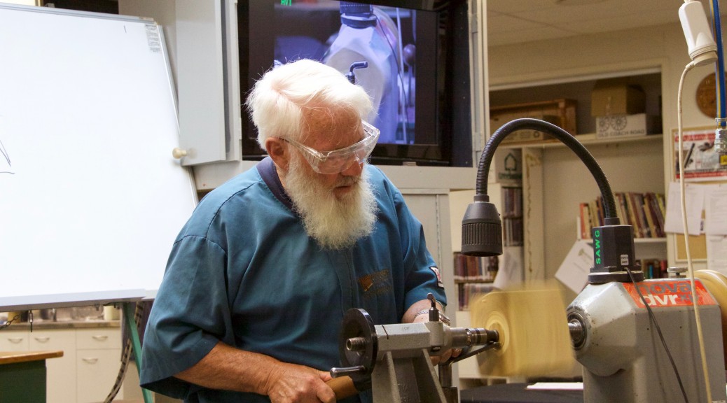
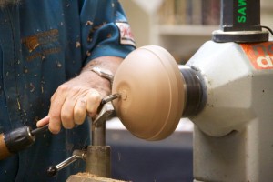
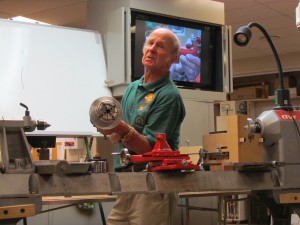
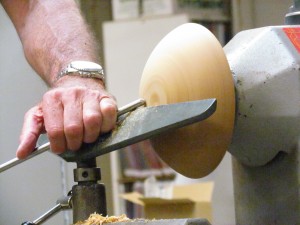
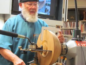
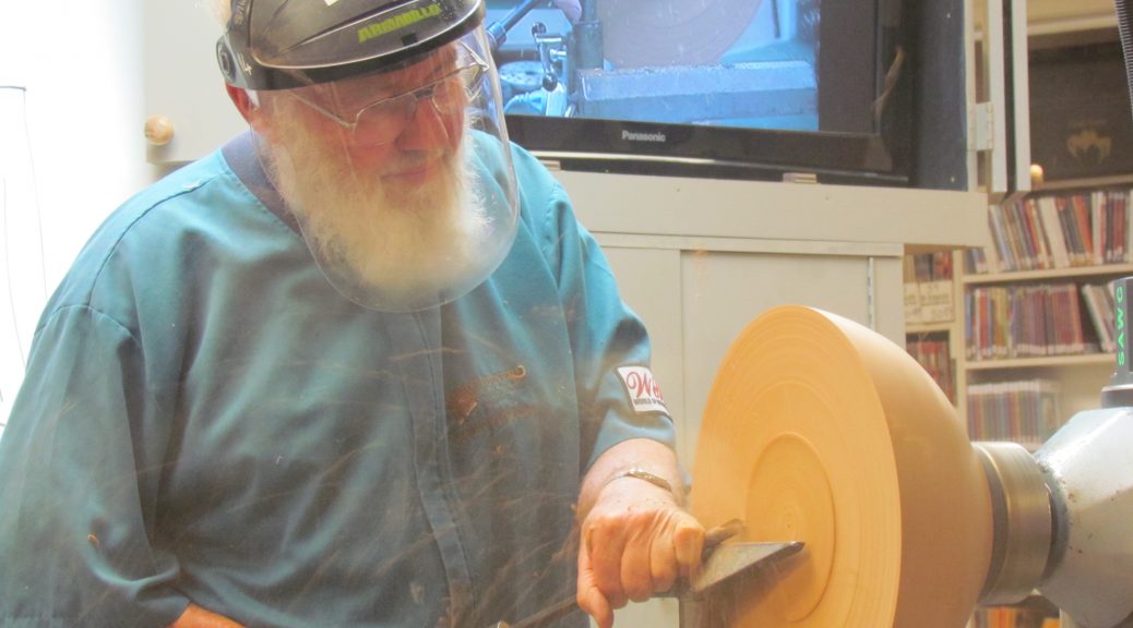
IMG_0876Dick kicked off by giving an overview of the business end – discussing the various clearance angles and rakes on the cutters of three bowl-savers. Two New Zealand manufactured products were on display: Woodcut Bowlsaver and the McNaughton Centre Saver, in addition Dick also covered the cutter on the Oneway, a Canadian coring system.   IMG_0879
Having owned and used the Woodcut I was keen the see the McNaughton demonstrated but unfortunately the handle was missing in action. This tool appears to offer greater options for coring but Dick stressed this is a judgement tool, that may take some time to become familiar with. Sourcing may also be an issue.  Carbatec are the distributors for Kelton Industries.  Also check the Library for a Mike Mahoney DVD on the McNaughton Centre Saver.
Onto the Woodcut.  Dick covered off the assembly and also showed the difference between the Guild’s bowl-saver and his own which has been modified to accept a longer cutting blade that Woodcut now offer.  Sharp is key with a quick refresher on honing the Steelite tip was useful.

IMG_0886

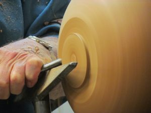
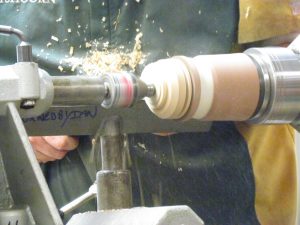
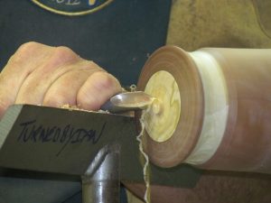
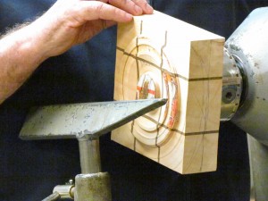
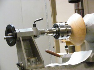
Mounting a blank of kauri roughly 350 in diameter Dick commented that he has managed to bowl save up to six bowls from one blank with the Woodcut. Forming a spigot – another useful tip noted was that by using larger chuck jaws these are able to absorb the cutting pressure better when bowl saving. It is recommended finishing the outside of the bowl and if coring green wood this can be achieved by wet sanding. Use of a reversing mandrel makes remounting the blank more accurate – another item for the tool kit.

IMG_0887

One thing I have noted with purchasing kiwi made woodturning tools is that the manufacturers in the main have good written instructions and advice on setup and use. I still have the video on my early Woodcut Bowl Saver and the advice in the early booklet on setup discusses using callipers to determine the mounting/cutting position. The later models offer templates to assist with setup or an optional extra is a laser guide.

IMG_0888

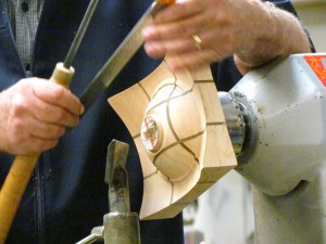
Setting the lathe to 500-600rpm in this instance the general thrust, no pun intended, is nice and steady using the body where possible to support the cutting pressure. With the pivot point set some 20mm towards the turner, the longer blade, in this instance, allowed for a clean cut right to the centre rather than having to knock the inner core out if the shorter blade had been used.

Time passed quickly and this was a timely refresher as I have some bowl saving to do coincidentally it is pepper wood that I am planning on coring. Thanks Dick another insightful demo.
Into the Blender – Gary McDonald

Club Meeting: 13 April 2016
Report by: Philip Johnstone

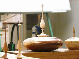
This was a very informative demo by Gary, showing us how to make finials. He started by pulling out some finials that he has made in the past, and it soon became obvious that he has had a lot of practice with them!

IMG_0785

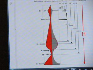
Next he moved on to showing us the mathematics behind the perfect finial, and such calculations are not for the faint-hearted! He toned down the technicalities by teaching us the six “control points” on a finial. These basically take a set ratio, apply it to the length of the finial, mix it all together in a calculator, and out comes the diameter of the desired finial.

IMG_0791

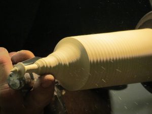
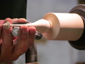
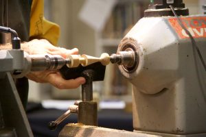
He then moved on to the lathe, and started turning. Starting from the tip of the finial, he slowly worked his way to the base, checking his measurements each time he got to a control point. As he was doing different parts, he demonstrated how to use different tools, and showed a considerable skill in thin turning.

IMG_0803IMG_0810IMG_0816

It was a well-presented demonstration, and Garry kept a lively dialogue going throughout. An enjoyable evening in all.


Inserted Lidded Box – Ian Outshoorn

Club Meeting:    6 April 2016
Report By:  Murray Wilton

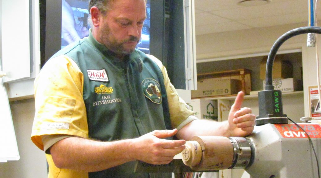
Well known to our members, Ian is from the North Shore Guild. He began his demo by showing us a mock-up of the finished article in solid form. This was to give an idea of outer shape and form, as well as to illustrate what the finished lid insert would look like. The “box” could be described as tiny, measuring about 75 X 75 X 75.

Wear a safety mask! Ian is strong on the need for safety in the workplace and he carried out his demo with the full gear in place.
IMG_0724
Ian starts with a block 90 X 90 X 120 which allows plenty of waste and allowance for any blunders which can happen when working with small pieces. Choose a darker timber to produce a contrast with the insert. Small work of this kind is enhanced by using a chuck and/or live centre at each end. Held in a chuck at the headstock end and a live centre at tailstock end allows initial roughing down to round to be achieved accurately. Ian then replaces the live centre with a drill chuck holding a 48mm Forstner bit to make an initial hole for the lid insert, about 10 mm deep. This means the tailstock end is the lid end of the starting block. The hole must be drilled carefully and the drill must be sharp as Forstner bits sometimes tear the timber. (“This is my way”, Ian responded to those who suggested it might be easier to simply turn the insert with a suitable chisel.)

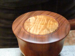
The insert is produced by fixing a glue block into the chuck with a 50 X 50 X 15 mm piece of contrasting timber (rewarewa or copper beech in Ian’s case) glued with Titebond to the outer face. The insert also serves as a spigot for later use. The glue block can be turned at a relatively high speed because of its small diameter. Using a parting tool the insert on the glue block is trimmed to same diameter as the 48 mm Forstner hole. It must be a perfect fit so great care has to be taken. Also, the insert has to bottom out in the main block hole so make sure it isn’t too thin. Leave enough clear to make a spigot.

Next mark the glue block with “top” and “bottom” at each end of the insert grain to ensure insert and main block grains line up when the two blocks come together. Place the main block in a second chuck at the tailstock end and line up with the glue block so grains are in same direction. Apply superglue to the edges only of the insert and wind the tailstock in to meet the headstock and fit the pieces firmly together.

When dry, remove from both chucks and insert the main block and glue block together into the headstock chuck, using a live centre at tailstock end to hold the insert. (You are totally confused by this stage so please study Ross Johnson’s excellent photos to see what I’m trying to tell you!) Now begin turning the whole assembly to the desired final box diameter (about 75 mm).
IMG_0732
This is where you need to be clear about the depth of the lid insert so that when you part off the lid you will know whether or not the insert will show on the under side of the lid (your choice). Mark the desired depth of the lid (say 10 mm) and use a 10 mm bowl gouge to turn the lid to required outer shape. Turn a spigot in the insert above the top line of the lid. When completed, part off the lid at the marked line and use a draw saw (available from Carbatec) to complete the cut, slowly and carefully to avoid burning.
IMG_0738
Re-position the now separate lid in the headstock chuck using the spigot you have just turned and finish lid to desired shape. This means any hollowing you want in the lid as well as the rebate which will position the lid snugly on the base. Now replace the base of the box in the chuck, bottom end to headstock. Carefully measure the lid inside diameter (of rebate) and mark where the hollowing edge has to finish to ensure the box rebate fits perfectly to the lid rebate. Before starting the box hollowing, jam-fit the lid on the box, rebate-to-rebate, with the grains lined up. This is so that you can finish off the lid. The lid end (glue block still attached) is held by a live centre in the tailstock. Tape the joint to avoid any tendency to twist during the lid finishing work. Part off most of the glue block, withdraw the tailstock and live centre and complete finishing work to top of lid. Normally turn from centre of lid outwards, but if this causes tearing of the insert, work the other way. At this stage add beads if you want them.IMG_0741IMG_0745

Complete the job by removing the lid and finish the hollowing of the box as well as any external finishing needed. Finally part off the bottom of the box.
IMG_0749
Ian warned that making small lidded boxes is delicate work requiring a great deal of patience and careful turning. After making several of these little pieces, Ian says he is still learning, so don’t be discouraged if your first attempt isn’t a raving success. Thanks, Ian, for a top-of-the-class demo.

Inside Outside – Bruce Wood

Club Meeting: 23 March 2016
Report by: Richard Johnstone

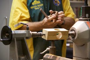
Bruce began his demonstration by showing us some pre-prepared examples of his work. Each was hollow with different shapes cut out of the walls. His demonstration example was hollow with a tree in the centre.

He began with four identical pieces of wood. 33mm square by 220mm long. Each piece had been carefully prepared so that each surface was clean, flat and square. These are glued together on the long sides to get them ready for putting on the lathe


Tip: Bruce doesn’t use a Paper join and explains that his way is easier to separate. All that is required is a small dot of Titebond glue at each end of the pieces to be joined. These are then clamped to ensure a firm hold. After the first turning has been completed, the ends can be cut off and the four pieces will either just come apart or are easily separated.

The glued pieces are put between centers using Steb centers. These are better than single point centers as they reduce the pressure in the middle and lessen the risk of the glued pieces separating.

Bruce carefully marked out the block and then began cutting the first hollow. He uses a cardboard cutout as a template to ensure accuracy. He then changed to using a 55 degree gouge for the bottom of the hollow because as he said, “it’s not so sharp on the point”.

IMG_0479

After completing the “inside” turning, Bruce cut off the ends and used a kitchen knife to split the pieces. They did come apart reasonably easily, but he may have used a bit more glue than necessary because he knew that it was going to be used for the demonstration and he didn’t want it to fly apart.

The pieces are then turned around and re-glued in pairs ready to have a Christmas tree inserted.

The tree was made from a 40mm long and 28mm diameter piece of Kauri. It was held between centers and had the tree shape made then grooved and sanded lightly. He then turned off the ends and power sanded the rough ends. The tree was painted appropriate colours with water based dye.

IMG_0490

With the tree complete it was now time to return to the two glued pieces. Bruce used a Dremel with a 5mm round bit to cut a groove in each side for the tree to fit. Trial and error soon had the grooves the correct size and the tree could be fitted and the pieces glued together and clamped. The effect was a brightly coloured Christmas tree inside a hollow cavity.

IMG_0498

Using a piece which he had prepared earlier, Bruce put it back on the lathe to shape the outside. He told us that he aimed to get an even thickness around the hollowed area without getting too thin. We all watched as he perfected the shape around the hollow and the walls continued to get thinner with each cut. But, he did it successfully and stopped before the fatal “final cut”.

IMG_0512

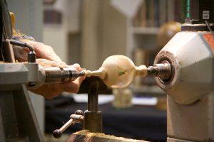
To finish, Bruce turned a small ball on the top and a finial on the bottom. He sanded it before the ends got too thin and then turned both ends thinly until nearly through. The final job was to cut off the ends and give a light sanding.

IMG_0517

It was a very good demonstration. Thank you to Bruce for all the time and effort to prepare and present his ideas.

Segments – Dave Hook

Club Meeting of 16 February 2016
Report by Jim Jackson

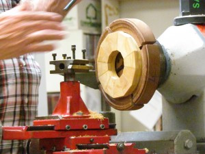
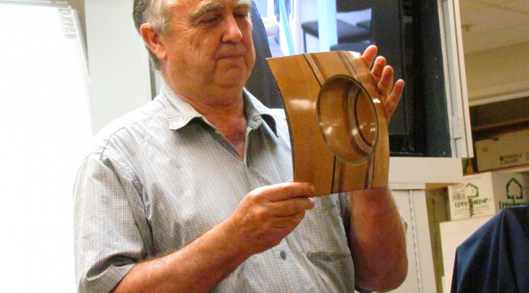
Dave gave the members an insight as to his past advising the members that he was born in the UK, trained in the UK as an Engineer working in metal. Emigrated to NZ 49 years and 11 months ago on a 2 year contract. He was inspired to start woodturning by his father. Dave was a founder member of Franklin Woodturners Club at Waiuku. Dave’s dad worked at the mill for 17 years and Dave beat him in service with 30 years. Dave made his first segmented turning at the club in Waiuku, it took 3 months to complete, and he was advised to put a high price on it.
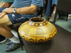
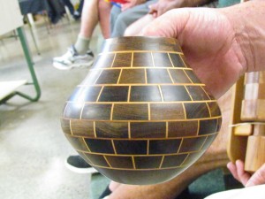
Dave handed out a segmented bowl to be passed around the audience.
IMG_0583
This bowl has over 300 pieces, the main ring has 10 elements to each segment, and Dave made another 4 bowls to the same pattern.
Dave gave out the following tips at this stage for advice:
Work out pattern to start with.
The books on segmented turning are generally very old, the glue used in the old days was made from boiling up horns, hair and hoofs in cast iron glue kettles, this glue has long setting times, the work probably was clamped with a hose clip, Dave subsequently used a yellow glue from Carbatec, now he uses a white exterior grade glue which grips faster, within half an hour he can machine it and being exterior it can go out in the rain. The segments are now clamped with elastic bands, more pressure will only squeeze out and waste the glue.
Use a jig (shown) or toggle clamps to hold segments for cutting with a drop saw or table saw, remember to remove any burrs.
All segments are cut with the drop saw and NOT sanded as the sanding creates ‘curved’ pieces.

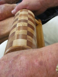
Dave was asked to make a rolling pin with segmented wood in a spiral form. It took 972 pieces, when the woman asked for another one similar he refused. Now he makes rolling pins with a slightly less onerous formation.
IMG_0601
Dave uses jigs to hold the segments together whilst assembling them on a flat surface.
Years ago Tecknatool made a device called an “Ornamental Turner”, which was sold by Carbatec. Now no longer available except at a high price on the internet.
Dave’s Missus gave permission for Dave to purchase something nice when he got out of hospital, so he purchased his device, he has subsequently added a toolbox to hold his cutters. The toolbox was made by Dave during his time at the machine shop. The ornamental turner ensures that his built up work will be parallel to the previous segment. Using the ornamental turner with the toolbox and homemade cutters Dave confirms that he does not have “dig ins” and the set-up is good for repetition work, he makes 50 wig stands at a time.
IMG_0592IMG_0595
Note the soft jaws made by Dave holding segmented work ready to be machined flat.
Dave passed around a bowl with 182 pieces measuring approx. 120mm diameter, wood is Rata and Kaikatea.
IMG_0599

Another tip to manufacture thin strips of wood (approx. 2mm thick) to look like a feather, take a thicker piece of scrap wood and thickness it then glue on your good wood, saw with a table saw to give say 3mm thick and then thickness to 2mm, add another good wood strip to the previous thin strip and continue in this fashion to however many strips you want. You can now use them in segmented work.
Dave’s demo was well received

At Least Three Woods – Dick Veitch

Club Meeting: 9 March 2016
Report by: Graeme Mackay

The task for this term was to use several types of wood in a turning project. Dick Veitch focused his demonstration on making wig stands with a comment that it is an item that is pleasurable to give away, fun to make and has a number of interesting challenges. Wig Stands are part of the “look good feel better” cancer recovery program which the SAWG club supports.

The making of wig stands; headpiece, stem and base, involves a number of techniques that include spindle turning, turning between centres and bowl work – and of course planning and measurement. A useful project to develop woodturning skills. The basic wig stand design plans and measurements are on the SAWG club website. The design has been developed to accommodate a stand that holds a full wig. The headpiece has to be wide enough to allow a wig to be easily placed over it and keep the fall of hair in place. Also, as experience has shown, there is a need for reasonable depth to allow the wig to flow off the head piece and fall freely.

The Headpiece: Dick placed the Matai block between centres and a chuck bite was made on the side that is to be top of the head. There is a need to give enough wood for the spigot and to allow for a second. Dick suggest to keep the speed quiet and making the initial spigot. The block is then reversed onto the spigot ready for rounding and shaping. A new spigot with a centering dimple is made. The dimple provides a guide for drilling the 25 mill hole to take the stem tenon. Dick suggested a 25 mm hole to allow the use of idle option of using an expansion jaws.

IMG_0436

Increasing the depth of the headpiece: If the blank/block for the headpiece does not have depth the next work is required. There are often bits of wood around the workshop that are “not quite” for the purpose designed. Then with some glue and lamination they can be joined to form a larger block with more depth. This is a good exercise to practice lamination skills – and your design skills. There are many options of both similar and contrasting wood.

IMG_0444

Base: Dick used a Pohutukawa blank for base. The heavy wood providing some stability to the wig stand. A base spigot is formed. The block then reversed onto the jaws for shaping and drilling the hole to take the stem Tenon. Dick referred a simple clean base with the design showing in the stem itself. A 25 mm hole is drilled to take stem and act as a hole to take expansion jaws.

Stem: Dick used a Tawa block for the stem. The measurements for the length of the stem are in the SAWG project guide. This is a good place to practice spindle work and application of design. After rounding the blank, the 25 mm tenons are marked off and made on each end to join the base and head.

IMG_0447

Stem Design: Dick discussed keeping the stem elements visually balanced, usually the thicker element on the bottom section. The simple demonstration design had pairs of beads with a key element bound by each bead. Dick then set up the marking for the initial cuts that frame the beads. The middle section was divided into thirds and the Ogee curve mapped out. Dick expressed the need for patience and starting out on the beads. In this demonstration he used the Skew chisel to form the beads and finish with a standard spindle gouge. Care needs to be taken with the main cove. Planning the cutting process for the individual elements on the stem is productive and helps in avoiding uneven elements.

In summary Dick made the following comments:
The Wig Stand offers a useful woodturning exercise.
Planning and marking pays off.
Thinking through the process again pays off.
And a bit of patience helps the end product.

Wig Stand Project Sheet
Wig Stand Spindle Ideas

Top Gears Unmasked – Fred Irvine

Top Gears Unmasked by Fred Irvine, Hamilton Woodturners Guild
Club Meeting: 2 March 2016
Report by Earl Culham

While waiting for the meeting to commence, I watched a couple of SAWG helpers bringing to the demonstration area, a number of strange pieces of equipment. As more and more bits and pieces were delivered my disquiet grew, how the hell was I going to report on this and make sense of it to fellow attendees who would later want to review the meeting, and those who had been unable to attend and who wanted to catch up. Whew, Bruce had handed me the hot potato tonight!

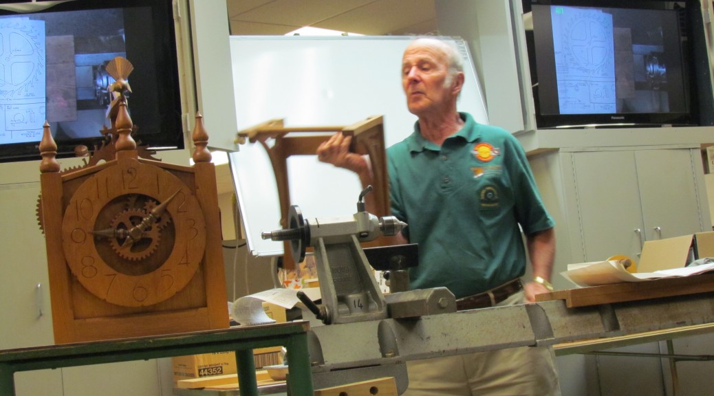
Fred commenced his demonstration with some reminiscing about attending the club close to its foundation in 1988; Mac was able to fill him in with the appropriate information. He then commented that each person who is a woodturner has their own favourite projects, whether it is making bowls or other objects which please the creator. His favourite has been in combining timbers and making objects such as gear wheels.

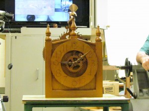
Fred displayed a large wooden clock that he had made some 30 years ago, as his first effort in making gears. The clock was a work of art, including a carved Chatham Island fantail and finials, which incidentally were added as embellishment and not part of the original plan. He cut the gears out using a scroll saw from a plan which he showed to the meeting.

IMG_0458

The instructions with the plan were to cut out the diagrams of the gears and paste them on  to the wood to be used. There is a snag in this method and Fred proceeded to demonstrate what that was.

Fred showed that a sheet of newspaper can be torn in a straight line if it is done down the page, but try to tear a straight line across the page and it won’t work. This of course, is due to the grain in the paper. He then produced two strips of paper the same width, one of which was placed in water to soak for a few minutes the other laid out flat. When the soaked piece was laid beside the control sample, the soaked piece was longer, indicating that paper expands with moisture by about 2.1%. Therefore, the suggestion in the instructions to paste the paper to a piece of timber would result in the gear being oversized and inaccurate.

When making his clock, Fred drew out the escapement wheel onto a piece of plastic, plotted 30 points for the cogs, then used this as a template to ensure that the gear was cut accurately.

IMG_0467

Selection of material to use is important, to make this clock, Fred chose rata. He said that if he was to make another clock, he would make the rata into a ply wood for stability.

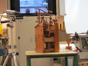
The clock usually hangs on the wall by a bracket which he showed to the meeting. The movement is powered by a large weight which has been encased in rata and has a pulley wheel on the top so that the weight can move on the cable or chain (not sure which Fred uses on his clock). The weight is rewound using a wooden key. A pendulum which is quite long has a sliding weight which can be used to adjust the time. The clock when it is working has a lovely sound.

Fred said he has no idea how many hours it took to make the clock using a scroll saw to cut out all of the gears, but it was an enjoyable experience and he learnt an awful lot during its construction.

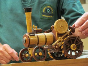
As an introduction to the next item in the demonstration, Fred showed a photograph of a traction engine with two large trailers loaded with wool bales. This traction engine towed the trailers on wooden wheels for 100 miles.  A beautifully made model traction engine was then produced.

IMG_0472

The engine was made by a fellow member of the Waikato guild with Fred assisting with the making of gears and wheels. The engine is a scale model made in different coloured wood with a moving piston, wheels and steering worm. It is a work of art.

Rather than using a scroll saw to make the gears as had been done for the clock, Fred now uses an ornamental cutter. This is attached to the headstock, and a complicated jig mounted on the lathe bed is used to hold the material which will be made into the gear. Unfortunately, the jig could not be fitted to the club lathe so a demonstration of its use was not possible. It would be very confusing if I tried to paint a word picture of this complicated apparatus so I won’t, but it certainly looked like a piece of equipment that was fit for purpose and that had taken a lot of thought and skill to make.

IMG_0483

Fred uses a book titled “Gears and Gear Cutting” by Ivan Lowe as a reference book, in his words, it is a very good book and easy to read.

The next piece of equipment produced for our edification assisted Fred in making the correct shape and size of the cutter used in the ornamental cutter. The cutter is quite small and difficult to shape without a method of making an enlargement of it. To do this, Fred made his own epidioscope. If like me, you had never heard of this piece of equipment, here is the Google definition:- The opaque projector, epidioscope, epidiascope or episcope is a device which displays opaque materials by shining a bright lamp onto the object from above. A system of mirrors, prisms and/or imaging lenses is used to focus an image of the material onto a viewing screen. By using the epidioscope, Fred is able to see where the shape is not quite right, mark the cutter with blue, and then reshape as needed.

Last but not least, another piece of machinery was produced which is used for cutting threads on objects such as screw topped lidded boxes, and was used to make the worm which operates the steering on the model traction engine. The tool has the capacity to make different threads as well as left hand threads. Examples of threaded wooden tools were shown including threaded clamps, wooden gauges and old lidded boxes which held threaded candle holders.

Thanks Fred for an interesting and informative  demonstration.

Square is Good – Warwick Day

Club Meeting: 24/02/2016
Report by: Mike Ainsworth

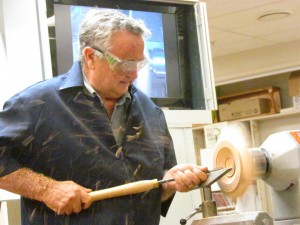
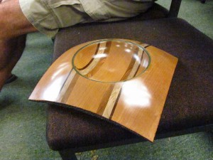
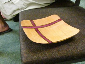
Warwick set out to demonstrate how a bland piece of Macrocarpa can be transformed into an interesting thing of beauty by showcasing the variety and effects that can be achieved by creating square edged bowls with laminated inserts.

Macrocarpa was used with narrow strips of hardboard laminated in an offset cross providing an interesting contrast of colour and texture.

IMG_0397

Accurate cutting is required for the laminating and one cut was made and glued and then left and then the cross cut and second lamination was made 24 hours later.

When turning, the 13mm gouge was used initially for more stability to minimise bouncing across the woods of varying hardness, and the tailstock was pulled up when possible using a fine bolt to allow for more access. The bowl was turned as normal and the outside edges were turned from outside to in, to avoid tearing out. (Harder wood than Mac would be more forgiving.)

IMG_0405IMG_0416

The finishing was done with the 10 mm gouge with care being taken to avoid catching the square corners and then a sharp scraper was used to smooth across the join between hard wood and soft.

Sanding started with the lathe at about 400 rpm and only the inner part was sanded with the more delicate outer part being done with the lathe stopped.

IMG_0395 IMG_0390Initially held on a 40mm chuck, the piece was reversed using the new vacuum chuck which provided a very quiet solid and stable platform to work on at about 700 rpm. They aren’t cheap but they are available from Terry.

All in all a highly entertaining and instructional demo. Thanks Warwick.
Footing It – John Whitmore

Club Meeting: 17 February 2016
Report by: Bill Alden

John opened his talk with a bit of history going back to a 1999 symposium where he won a prize for mixed media much to the annoyance of some  of the more experienced  turners.
He then brought some samples and asked which we felt was the most attractive. The ones adding lift to the bowl were more attractive than those with heavy bottoms.. There also needs to be a crispness and a seamless transition from one wood to the next and the overall shape needs to be followed.

The following are reasons for adding a foot or an extra piece of wood on the bottom of a bowl

  1. Extending a shallow piece of wood
  2. Strengthening weak bases mainly on burrs
  3. Extending the bottom of a bowl which has been cut too thin.
  4. Facilitates concurrent inside/outside enabling concentricity using the same amount
  5. Truing up a warped bowl.
  6. When bowl saving the inner core is easier to use when a foot is glued on.

IMG_0033Design considerations

It was also decided that a darker foot on a lighter bowl look better than a lighter foot on a darker bowl. It was decided that the reason for this being that we expect light to come from above.

Grain alignment is important. In addition to placing a foot on a bowl a second wood type can be used on the rims of bowls. These wooden rims can be cut from the outside of a bowl blank when the base is being turned.

John first lined up the headstock and tailstock using an Acculine, this is important to be able to get an accurate finish he then used a piece of teak decking offcut in the jaws using a packer for the depth of the jaws he faced it off and turned it round to the size of the bowl he was going to put it on.

John then used the Granville Harworth method of sanding which consisted of stick on sandpaper pieces onto a square section aluminium section he used two grades on separate pieces of aluminium Square section. The tool rest was used as a guide to lightly sand the bottom with the two grades of sandpaper, not much pressure was applied in this process.

IMG_0050

This was left on the chuck and the bowl (which was a core from a bowl saving exercise) was mounted on a faceplate and the bottom trued up to the size of the pre-prepared foot leaving the bottom slightly concave which helps to stabilise the sanding process. The base of the bowl was then sanded using the same process. Grooves were then applied to aid keying of the glue. Brush or air blast both surfaces before applying the glue, he used ordinary white aliphatic PVA.

The foot which was on the other chuck was reversed into the tailstock with a Morse taper onto which was screwed the chuck. The end grain of both pieces should now be marked with a felt pen to enable lining up of the foot and the bowl. The glue was now applied fairly liberally protecting the bed with a paper towel from any glue drips. The foot is now brought up to the bowl and rotated as the glue starts to grab finally adding a small amount of pressure once the grain was lined up. The glue should be dry in about 20 minutes but John advises to leave this set up on the lathe overnight to ensure that the bond is fully cured.

IMG_0057

The following week John brought in the bowl which was only left on the lathe until the guild closed and when turning it found that it was adequately glued and the joint was nice and crisp and accurate.

This is the method that John uses now after experimenting with lots of different methods with a recesses both 2 mm and 10 mm are using a pin off the lathe as a locator pin. He finds that this method is simple and has never had a failure.